
User manual

Inverse Multiplexing for ATM (IMA)
MPC8260 PowerQUICC II Family Reference Manual, Rev. 2
Freescale Semiconductor 33-39
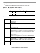
33.4.4.2.2 IMA Group Receive State (IGRSTATE)
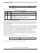
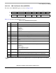
The fields of the IGRSTATE register are shown in Figure 33-18.
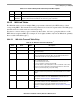
Table 33-12 describes the IGRSTATE bit fields.
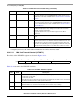
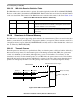
33.4.4.2.3 IMA Receive Group Frame Size
The fields of the IRGFS register are shown in Figure 33-19.
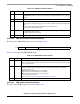
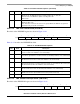
Table 33-11. IGRCNTL Field Descriptions
Bits Name Description
0 GOTP Group order table pointer. Defines which group order table pointer (RGRPORDER0 or
RGRPORDER1) will be used for the cell extraction round-robin. Initialize to zero at group
startup.
1–2 — Reserved, initialize to zero.
3-4 RXSC Receive status/control. Sets the receive mode of the IMA group.
00 Filler mode. The IMA group processes only ICP cells. Data cells are replaced with filler
cells.
01 Active mode. The IMA group is capable of receiving data cells.
1X Reserved. Defaults to Filler Mode.
5 IDCR IDCR recovery enable. Selects the mode of the receive process activation function.
0 On-demand cell processing
1 IDCR-regulated cell processing
6-7 — Reserved, initialize to zero.
0123 7
Field IDCR_DN GDSS —
Figure 33-18. IMA Group Receive State (IGRSTATE)
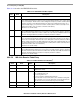
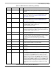
Table 33-12. IGRSTATE Field Descriptions
Bits Name Description
0 IDCR_DN IDCR Done. Microcode-managed parameter. When this bit is set by the microcode, the TRLR
value is valid and can be used to program the IDCR timer entry values for this group. Initialize
to zero at group startup.
1-2 GDSS Group delay synchronization state. Initialize to zero at group startup. Must be changed by
software to 01 after sufficient links have achieved frame synchronization. Subsequently
managed by microcode.
00 Group delay synchronization process inhibited.
01 Group delay synchronization process enabled.
10 Group delay synchronization process in progress.
11 Group delay synchronized.
Refer to Section 33.5.4.10, “Receive Event Response Procedures.”
3-7 — Reserved, initialize to zero.