
User manual

Serial Peripheral Interface (SPI)
MPC8260 PowerQUICC II Family Reference Manual, Rev. 2
Freescale Semiconductor 38-9
with LEN=7 (data size=8), the following data is selected:
msb ghij_klmn__opqr_stuv lsb
the data string is selected:
msb ghij_klmn__opqr_stuv lsb
with REV=0, the string transmitted, a byte at a time with lsb first is:
first nmlk_jihg__vuts_rqpo last
with REV=1, the string is byte reversed and transmitted, a byte at a time, with lsb
first:
first ghij_klmn__opqr_stuv last
Example 3
with LEN=0xC (data size=13), the following data is selected:
msb ghij_klmn__xxxr_stuv lsb
the data string selected is:
msb r_stuv__ghij_klmn lsb
with REV=0, the string transmitted, a byte at a time with lsb first is:
first nmlk_jihg__vuts_r last
with REV=1, the string is half-word reversed:
msb nmlk_jihg__vuts_r lsb
and transmitted a byte at a time with lsb first:
first r_stuv_ghij_klmn last
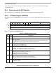
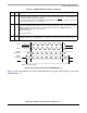
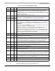
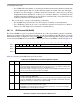
38.4.2 SPI Event/Mask Registers (SPIE/SPIM)
The SPI event register (SPIE) generates interrupts and reports events recognized by the SPI. When an
event is recognized, the SPI sets the corresponding SPIE bit. Clear SPIE bits by writing a 1—writing 0 has
no effect. Setting a bit in the SPI mask register (SPIM) enables and clearing a bit masks the corresponding
interrupt. Unmasked SPIE bits must be cleared before the CP clears internal interrupt requests. Figure 38-7
shows both registers.
Table 38-3 describes the SPIE/SPIM fields.
01234567
Field — MME TXE — BSY TXB RXB
Reset 0000_0000
R/W R/W
Addr 0x0x11AA6 (SPIE); 0x0x11AAA (SPIM)
Figure 38-7. SPIE/SPIM—SPI Event/Mask Registers
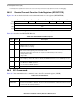
Table 38-3. SPIE/SPIM Field Descriptions
Bits Name Description
0–1 — Reserved, should be cleared.
2 MME Multimaster error. Set when SPISEL
is asserted externally while the SPI is in master mode.
3 TXE Tx error. Set when an error occurs during transmission.
4 — Reserved, should be cleared.
5 BSY Busy. Set after the first character is received but discarded because no Rx buffer is available.