
User manual

I
2
C Controller
MPC8260 PowerQUICC II Family Reference Manual, Rev. 2
39-2 Freescale Semiconductor
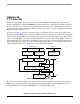
39.1 Features
The following is a list of the I
2
C controller’s main features:
• Two-signal interface (SDA and SCL)
• Support for master and slave I
2
C operation
• Multiple-master environment support
• Continuous transfer mode for automatic scanning of a peripheral
• Supports a maximum clock rate of 2,080 KHz (with a CPM utilization of 25%), assuming a
100-MHz system clock.
• Independent, programmable baud-rate generator
• Supports 7-bit I
2
C addressing
• Open-drain output signals allow multiple master configuration
• Local loopback capability for testing
39.2 I
2
C Controller Clocking and Signal Functions
The I
2
C controller can be configured as a master or slave for the serial channel. As a master, the controller’s
BRG provides the transfer clock. The I
2
C BRG takes its input from the BRG clock (BRGCLK), which is
generated from the CPM clock; see Section 10.8, “System Clock Control Register (SCCR).”
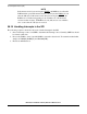
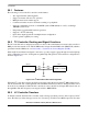
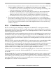
SDA and SCL are bidirectional signals connected to a positive supply voltage through an external pull-up
resistor. When the bus is free, both signals are pulled high. The general I
2
C master/slave configuration is
shown in Figure 39-2.
Figure 39-2. I
2
C Master/Slave General Configuration
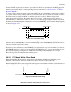
When the I
2
C controller is master, the SCL clock output, taken directly from the I
2
C BRG, shifts receive
data in and transmit data out through SDA. The transmitter arbitrates for the bus during transmission and
aborts if it loses arbitration. When the I
2
C controller is a slave, the SCL clock input shifts data in and out
through SDA. The SCL frequency can range from DC to BRGCLK/48.
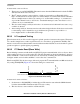
39.3 I
2
C Controller Transfers
To initiate a transfer, the master I
2
C controller sends a message specifying a read or write request to an I
2
C
slave. The first byte of the message consists of a 7-bit slave port address and a R/W request bit. Note that
V
DD
V
DD
Master Slave
(EEPROM, for example)
SCL SCL
SDASDA