
User manual

I
2
C Controller
MPC8260 PowerQUICC II Family Reference Manual, Rev. 2
39-4 Freescale Semiconductor
A master write occurs as follows:
1. The master core sets I2COM[STR]. The transfer starts when the SDMA channel loads the Tx FIFO
with data and the I
2
C bus is not busy.
2. The I
2
C master generates a start condition—a high-to-low transition on SDA while SCL is
high—and the transfer clock SCL pulses for each bit shifted out on SDA. If the master transmitter
detects a multiple-master collision (by sensing a ‘0’ on SDA while sending a ‘1’), transmission
stops and the channel reverts to slave mode. A maskable interrupt is sent to the master’s core so
software can try to retransmit later.
3. The slave acknowledges each byte and writes to its current receive buffer until a new start or stop
condition is detected.
4. After sending each byte, the master monitors the acknowledge indication. If the slave receiver fails
to acknowledge a byte, transmission stops and the master generates a stop condition—a
low-to-high transition on SDA while SCL is high.
39.3.2 I
2
C Loopback Testing
When in master mode, an I
2
C controller supports loopback operation for master write requests. The master
I
2
C controller simply issues a write request directed to its own address (programmed in I2ADD). The
master’s receiver monitors the transmission and reads the transmitted data into its receive buffer. Loopback
operation requires no special register programming.
39.3.3 I
2
C Master Read (Slave Write)
Before initiating a master read with the PowerQUICC II, prepare a transmit buffer of size n+1 bytes, where
n is the number of bytes to be read from the slave. The first transmit byte should be initialized to the slave
address with R/W = 1. The next n transmit bytes are used strictly for timing and can be left uninitialized.
Configure suitable receive buffers and BDs to receive the slave’s transmission.
If the PowerQUICC II is the slave target of the read, prepare the I
2
C transmit buffers and BDs and activate
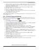
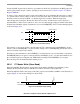
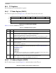
it by setting I2COM[STR]. Figure 39-5 shows the timing for a master read.
Figure 39-5. I
2
C Master Read Timing
A master read occurs as follows:
1. Set the master’s I2COM[STR] to initiate the read. The transfer starts when the SDMA channel
loads the transmit FIFO with data and the I
2
C bus is not busy.
2. The slave detects a start condition on SDA and SCL.
SDA Data ByteDevice Address
R
S
T
O
P
S
T
A
R
T
N
O
A
C
K
A
C
K
Note: After the nth data byte, the master does not acknowledge the slave.