
User manual

I
2
C Controller
MPC8260 PowerQUICC II Family Reference Manual, Rev. 2
39-8 Freescale Semiconductor
Table 39-4 describes the I2CER/I2CMR fields.
39.4.5 I
2
C Command Register (I2COM)
The I
2
C command register, shown in Figure 39-10, is used to start I
2
C transfers and to select master or
slave mode.
Table 39-5 describes I2COM fields.
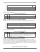
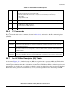
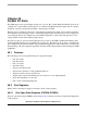
0 234567
Field — TXE — BSY TXB RXB
Reset 0000_0000
R/W R/W
Addr 0x0x11870(I2CER)/0x0x11874 I2CMR)
Figure 39-9. I
2
C Event/Mask Registers (I2CER/I2CMR)
Table 39-4. I2CER/I2CMR Field Descriptions
Bits Name Description
0–2 — Reserved and should be cleared.
3 TXE Tx error. Set when an error occurs during transmission.
4 — Reserved and should be cleared.
5 BSY Busy. Set after the first character is received but discarded because no Rx buffer is available.
6 TXB Tx buffer. Set when the Tx data of the last character in the buffer is written to the Tx FIFO. Two
character times must elapse to guarantee that all data has been sent.
7 RXB Rx buffer. Set after the last character is written to the Rx buffer and the RxBD is closed.
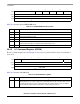
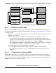
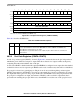
01234567
Field STR — M/S
Reset 0000_0000
R/W R/W
Addr 0x0x1186C
Figure 39-10. I
2
C Command Register (I2COM)
Table 39-5. I2COM Field Descriptions
Bits Name Description
0 STR Start transmit. In master mode, setting STR causes the I
2
C controller to start sending data from the
I
2
C Tx buffers if they are ready. In slave mode, setting STR when the I
2
C controller is idle causes it
to load the Tx data register from the I
2
C Tx buffer and start sending when it receives an address
byte that matches the slave address with R/W = 1. STR is always read as a 0.