
User manual

I
2
C Controller
MPC8260 PowerQUICC II Family Reference Manual, Rev. 2
39-10 Freescale Semiconductor
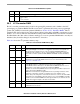
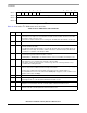
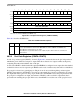
Figure 39-11 shows the RFCR/TFCR bit fields.
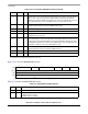
Table 39-7 describes the RFCR/TFCR bit fields.
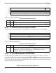
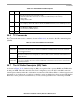
0x10 RBPTR Hword RxBD pointer. Points to the next descriptor the receiver transfers data to when it is in
an idle state or to the current descriptor during frame processing for each I
2
C channel.
After a reset or when the end of the descriptor table is reached, the CP initializes
RBPTR to the value in RBASE. Most applications should not write RBPTR, but it can
be modified when the receiver is disabled or when no receive buffer is used.
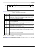
0x12 RCOUNT Hword Rx internal byte count
2
is a down-count value that is initialized with the MRBLR value
and decremented with every byte the SDMA channels write.
0x14 RTEMP Word Rx temp.
2
Reserved for CP use.
0x18 TSTATE Word Tx internal state.
2
Reserved for CP use.
0x1C TPTR Word Tx internal data pointer
2
is updated by the SDMA channels to show the next address
in the buffer to be accessed.
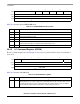
0x20 TBPTR Hword TxBD pointer. Points to the next descriptor that the transmitter transfers data from when
it is in an idle state or to the current descriptor during frame transmission. After a reset
or when the end of the descriptor table is reached, the CP initializes TBPTR to the value
in TBASE.Most applications should not write TBPTR, but it can be modified when the
transmitter is disabled or when no transmit buffer is used.
0x22 TCOUNT Hword Tx internal byte count
2
is a down-count value initialized with TxBD[Data Length] and
decremented with every byte read by the SDMA channels.
0x24 TTEMP Word Tx temp.
2
Reserved for CP use.
0x34 SDMATMP Word SDMA temp.
2
Reserved for CP use.
1
From the pointer value programmed in I2C_BASE at IMMR + 0x8AFC.
2
Normally, these parameters need not be accessed.
01234567
Field GBL BO TC2 DTB —
Reset 0000_0000
R/W R/W
Addr I2C_BASE + 04 (RFCR)/I2C_BASE + 05 (TFCR)
Figure 39-11. I
2
C Function Code Registers (RFCR/TFCR)
Table 39-7. RFCR/TFCR Field Descriptions
Bits Name Description
0–1 — Reserved, should be cleared.
2 GBL Global access bit
0 Disable memory snooping
0 Enable memory snooping
Table 39-6. I
2
C Parameter RAM Memory Map (continued)
Offset
1
Name Width Description