
User manual

System Interface Unit (SIU)
MPC8260 PowerQUICC II Family Reference Manual, Rev. 2
4-36 Freescale Semiconductor
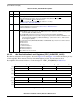
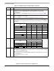
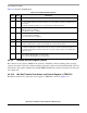
4.3.2.7 Internal Memory Map Register (IMMR)
The internal memory map register (IMMR), shown in Figure 4-29, contains identification of a specific
device as well as the base address for the internal memory map. Software can deduce availability and
location of any on-chip system resources from the values in IMMR. PARTNUM and MASKNUM are
mask programmed and cannot be changed for any particular device.
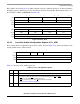
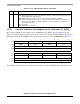
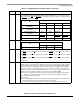
Table 4-13 describes IMMR fields.
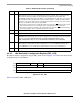
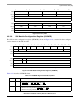
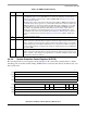
18 LPBSE Local bus parity byte select enable.
0 Parity byte select is disabled. LGPL4 output of UPM is available for memory control.
1 Parity byte select is enabled. LGPL4 pin is used as local bus parity byte select output from the
PowerQUICC II.
19–31 — Reserved, should be cleared.
0 14 15
Field ISB —
Reset Depends on reset configuration sequence. See Section 5.4.1, “Hard Reset Configuration Word.”
R/W R/W
Addr 0x0x101A8
16 23 24 31
Field PARTNUM MASKNUM
Reset 0x0011 (.29µm Rev A.1); 0x0023 (.29µm Rev B.3); 0x0024 (.29µm Rev C.2); 0x0060 (.25µm Rev A.0)
R/W R
Addr 0x101AA
Figure 4-29. Internal Memory Map Register (IMMR)
Table 4-12. SIUMCR Register Field Descriptions (continued)
Bits Name Description