
User manual

System Interface Unit (SIU)
MPC8260 PowerQUICC II Family Reference Manual, Rev. 2
4-42 Freescale Semiconductor
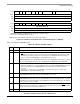
4.3.2.12 Local Bus Transfer Error Status and Control Register 1 (L_TESCR1)
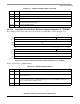
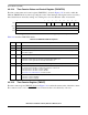
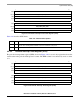
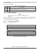
The local bus transfer error status and control register 1 (L_TESCR1) is shown in Figure 4-33.
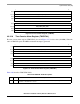
The L_TESCR1 register bits are described in Table 4-17.
01234 567 91011 15
Field BM — PAR — WP — TC — TT
Reset 0000_0000_0000_0000
R/W R/W
Addr 0x0x10048
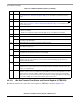
16 17 18 19 20 21 31
Field — DMD — DER
1
—
Reset 0000_0000_0000_0000
R/W R/W
Addr 0x1004A
1
.29µm (HiP3) Rev B.3 silicon and forward. Reserved on .29µm Rev A.1 devices.
Note: Bits 0–15 and 19–23 are status bits and are cleared by writing 1s.
Figure 4-33. Local Bus Transfer Error Status and Control Register 1 (L_TESCR1)
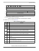
Table 4-17. L_TESCR1 Field Descriptions
Bits Name Description
0 BM Bus monitor time-out. Indicates that TEA
was asserted due to the local bus monitor time-out.
1 — Reserved, should be cleared.
2 PAR Parity error. Indicates that MCP was asserted due to parity error on the local bus. L_TESCR2[PB]
indicates the byte lane that caused the error and L_TESCR2[BNK] indicates which memory
controller bank was accessed.
3–4 — Reserved, should be cleared.
5 WP Write protect error. Indicates that a write was attempted to a local bus memory region that was
defined as read-only in the memory controller. Note that this alone does not cause TEA
assertion.
Usually, in this case, the bus monitor will time-out.
6 — Reserved, should be cleared.
7–9 TC Transfer code. Indicates the transfer code of the local bus transaction that caused the TEA
.
000 60x-local bridge
001 Reserved
010 Local DMA function code 0
011 Local DMA function code 1
1xx Reserved
10 — Reserved, should be cleared.
11–15 TT Transfer type. Indicates the transfer type of the local bus transaction that caused the TEA
.
Section 8.4.3.1, “Transfer Type Signal (TT[0–4]) Encoding,” describes the various transfer types.
16 — Reserved, should be cleared.