
User manual


Reset
MPC8260 PowerQUICC II Family Reference Manual, Rev. 2
5-4 Freescale Semiconductor
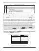
5.2 Reset Status Register (RSR)
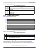
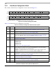
The reset status register (RSR), shown in Figure 5-2, is memory-mapped into the PowerQUICC II’s SIU
register map.
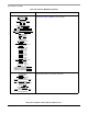
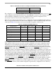
Table 5-3 describes RSR fields.
0 15
Field —
R/W R/W
Reset 0000_0000_0000_0000
Addr 0x10C90
16 25 26 27 28 29 30 31
Field — JTRS CSRS SWRS BMRS ESRS EHRS
R/W R/W
Reset 0000_0000_0000_0011
Addr 0x10C92
Figure 5-2. Reset Status Register (RSR)
Table 5-3. RSR Field Descriptions
Bits Name Function
0–25 — Reserved, should be cleared.
26 JTRS JTAG reset status. When the JTAG reset request is set, JTRS is set and remains set until software
clears it. JTRS is cleared by writing a 1 to it (writing zero has no effect).
0 No JTAG reset event occurred
1 A JTAG reset event occurred
27 CSRS Check stop reset status. When the core enters a checkstop state and the checkstop reset is enabled
by the RMR[CSRE], CSRS is set and it remains set until software clears it. CSRS is cleared by
writing a 1 to it (writing zero has no effect).
0 No enabled check stop reset event occurred
1 An enabled check stop reset event occurred
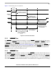
28 SWRS Software watchdog reset status. When a software watchdog expire event (which causes a reset) is
detected, the SWRS bit is set and remains that way until the software clears it. SWRS is cleared by
writing a 1 to it (writing zero has no effect).
0 No software watchdog reset event occurred
1 A software watchdog reset event has occurred
29 BMRS Bus monitor reset status. When a bus monitor expire event (which causes a reset) is detected,
BMRS is set and remains set until the software clears it. BMRS can be cleared by writing a 1 to it
(writing zero has no effect).
0 No bus monitor reset event has occurred
1 A bus monitor reset event has occurred