
User manual


Reset
MPC8260 PowerQUICC II Family Reference Manual, Rev. 2
5-8 Freescale Semiconductor
5.4.1 Hard Reset Configuration Word
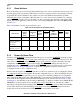
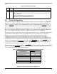
The contents of the hard reset configuration word are shown in Figure 5-4.
Table 5-7 describes hard reset configuration word fields.
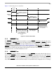
0 1 2 3 4 5 6 7 8 9 10 11 12 13 15
Field EARB EXMC CDIS EBM BPS CIP ISPS L2CPC DPPC — ISB
Reset 0000_0000_0000_0000
16 17 18 19 20 21 22 23 24 25 26 27 28 31
Field BMS BBD MMR LBPC APPC CS10PC ALD_EN
1
— MODCK_H
Reset 0000_0000_0000_0000
1
MPC8250, MPC8265, and MPC8266 only. Reserved on all other devices.
Figure 5-4. Hard Reset Configuration Word
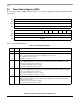
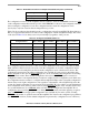
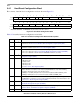
Table 5-7. Hard Reset Configuration Word Field Descriptions
Bits Name Description
0 EARB
1
External arbitration. Defines the initial value for ACR[EARB]. If EARB = 1, external arbitration is
assumed. See Section 4.3.2.2, “60x Bus Arbiter Configuration Register (PPC_ACR).”
1 EXMC External MEMC. Defines the initial value of BR0[EMEMC]. If EXMC = 1, an external memory
controller is assumed. See Section 11.3.1, “Base Registers (BRx).”
2 CDIS
1
Core disable. Defines the initial value for the SIUMCR[CDIS].
0 The core is active. See Section 4.3.2.6, “SIU Module Configuration Register (SIUMCR).”
1 The core is disabled. In this mode the PowerQUICC II functions as a slave.
3 EBM
1
External bus mode. Defines the initial value of BCR[EBM]. See Section 4.3.2.1, “Bus
Configuration Register (BCR).”
4–5 BPS Boot port size. Defines the initial value of BR0[PS], the port size for memory controller bank 0.
00 64-bit port size
01 8-bit port size
10 16-bit port size
11 32-bit port size
See Section 11.3.1, “Base Registers (BRx).”
6CIP
1
Core initial prefix. Defines the initial value of MSR[IP]. Exception prefix. The setting of this bit
specifies whether an exception vector offset is prepended with Fs or 0s. In the following
description,
nnnnn
is the offset of the exception vector.
0 MSR[IP] = 1 (default). Exceptions are vectored to the physical address 0xFFF
n_nnnn
1 MSR[IP] = 0 Exceptions are vectored to the physical address 0x000
n_nnnn
.
7 ISPS
1
Internal space port size. Defines the initial value of BCR[ISPS]. Setting ISPS configures the
PowerQUICC II to respond to accesses from a 32-bit external master to its internal space. See
Section 4.3.2.1, “Bus Configuration Register (BCR).”
8–9 L2CPC
1
L2 cache pins configuration. Defines the initial value of SIUMCR[L2CPC]. See Section 4.3.2.6,
“SIU Module Configuration Register (SIUMCR).”
10–11 DPPC
1
Data parity pin configuration. Defines the initial value of SIUMCR[DPPC]. For more details refer
to Section 4.3.2.6, “SIU Module Configuration Register (SIUMCR).”
12 — Reserved, should be cleared.