
User manual


The 60x Bus
MPC8260 PowerQUICC II Family Reference Manual, Rev. 2
8-4 Freescale Semiconductor
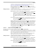
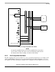
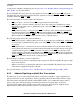
operations and maintains coherency between the primary caches and main memory. Figure 8-2 shows how
an external processor is attached to the PowerQUICC II.
Figure 8-2. 60x-Compatible Bus Mode
8.3 60x Bus Protocol Overview
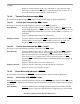
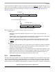
Typically, 60x bus accesses consist of address and data tenures, which in turn each consist of three
phases—arbitration, transfer, and termination, as shown in Figure 8-3.. The independence of the tenures is
indicated by showing the data tenure overlap the next address tenure, which allows split-bus transactions
to be implemented at the system level in multiprocessor systems. Figure 8-3 shows a data transfer that
consists of a single-beat transfer of as many as 256 bits. Four-beat burst transfers of 32-byte cache blocks
BR
BG
TS
A[0–31]
TT[0–4]
TSIZ[0–3]
TBST
CI
WT
GBL
AACK
ARTRY
DBG
D[0–63]
DP[0–7]
TA
TEA
PowerQUICC II
I/O
MEM
Data + Attributes
Address + Attributes
Memory Controller Signals
External Device
BR
BG
DBG
Latch
Latch &
DRAM MUX
Memory Control Signals
AP[0–3]
TS
APE