
User manual

The 60x Bus
MPC8260 PowerQUICC II Family Reference Manual, Rev. 2
8-14 Freescale Semiconductor
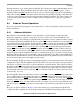
Each data beat is terminated with an assertion of TA.
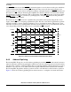
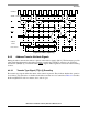
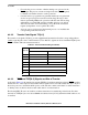
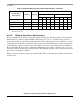
8.4.3.5 Effect of Alignment on Data Transfers
Table 8-6 lists the aligned transfers that can occur to and from the PowerQUICC II. These are transfers in
which the data is aligned to an address that is an integer multiple of the size of the data. For example,
Table 8-6 shows that 1-byte data is always aligned; however, a 4-byte word must reside at an address that
is a multiple of 4 to be aligned.
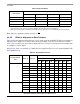
In Figure 8-6, Table 8-6, and Table 8-7, OP0 is the most-significant byte of a word operand and OP7 is the
least-significant byte.
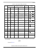
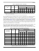
Table 8-5. Burst Ordering
Data Transfer
Double-Word Starting Address:
A[27–28] = 00
1
1
A[27–28] specifies the first double word of the 32-byte block being transferred; any subsequent double words must
wrap-around the block. A[29–31] are always 0b000 for burst transfers by the PowerQUICC II.
A[27–28] = 01 A[27–28] = 10 A[27–28] = 11
1st data beat DW0
2
2
DW
x
represents the double word that would be addressed by A[27–28] =
x
if a nonburst transfer were performed.
DW1 DW2 DW3
2nd data beat DW1 DW2 DW3 DW0
3rd data beat DW2 DW3 DW0 DW1
4th data beat DW3 DW0 DW1 DW2
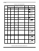
Table 8-6. Aligned Data Transfers
Program Transfer
Size
TSIZ[0–3] A[29–31]
Data Bus Byte Lanes
D0... ...D31 D32... ...D63
B0 B1 B2 B3 B4 B5 B6 B7
Byte 0001 0 0 0 OP0
1
—
2
——————
0001 0 0 1 — OP1 — — — — — —
0001 0 1 0 — — OP2 — — — — —
0001 0 1 1 — — — OP3 — — — —
0001 1 0 0 ————OP4———
0001 1 0 1 —————OP5——
0001 1 1 0 ——————OP6—
0001 1 1 1 ———————OP7
Half-Word 0010 0 0 0 OP0OP1——————
0010 0 1 0 — — OP2 OP3 — — — —
0010 1 0 0 ————OP4OP5——
0010 1 1 0 ——————OP6OP7