
User manual

PCI Bridge
MPC8260 PowerQUICC II Family Reference Manual, Rev. 2
Freescale Semiconductor 9-35
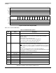
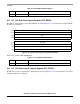
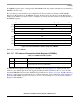
9.11.1.8 PCI General Control Register (PCI_GCR)
The PCI general control register (PCI_GCR), shown in Figure 9-22, contains a bit for controlling the PCI
reset signal when in host mode.
Figure 9-22. PCI General Control Register (PCI_GCR)
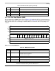
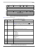
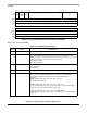
Table 9-9. describes PCI_GCR fields.
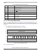
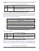
9.11.1.9 Error Status Register (ESR)
The error status register (ESR), shown in Figure 9-23, contains status bits for various types of error
conditions captured by the PCI bridge. Each status bit is set when the corresponding error condition is
captured. Each bit is cleared by writing a one.
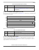
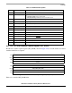
12–1 — Reserved, should be cleared.
0 LE_MODE Little endian mode. Controls the translation of 60x-PCI and PCI-60x. Refer to
Section 9.11.2.27.1, “Additional Information on Endianess” for more details.
0 Big endian mode.
1 Little endian mode.
31 16
Field —
Reset 0000_0000_0000_0000
R/W R/W
Addr 0x10882
15 10
Field — SPRST
Reset 0000_0000_0000_0000
R/W R/W
Addr 0x10880
Table 9-9. PCI_GCR Field Descriptions
Bits Name Description
31–1 — Reserved, should be cleared.
0 Soft PCI Reset Only valid when in host mode. Allows PCI_RST
to be controlled software.
Setting this bit drives the PCI reset signal high; clearing it drives the signal low.
Table 9-8. GPCR Field Descriptions (continued)
Bits Name Description