
User manual

PCI Bridge
MPC8260 PowerQUICC II Family Reference Manual, Rev. 2
9-56 Freescale Semiconductor
9.11.2.16 Subsystem Device ID Register
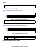
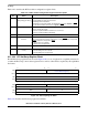
Figure 9-48 and Table 9-35 describe the subsystem ID register.
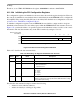
Figure 9-48. Subsystem Device ID Register
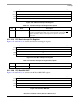
9.11.2.17 PCI Bus Capabilities Pointer Register
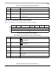
Figure 9-49 and Table 9-36 describe the PCI bus capabilities pointer register.
Figure 9-49. PCI Bus Capabilities Pointer Register
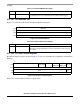
9.11.2.18 PCI Bus Interrupt Line Register
Figure 9-50 and Table 9-37 describes the PCI bus interrupt line register.
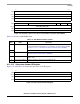
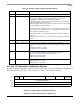
Table 9-34. Subsystem Vendor ID Register Description
Bits Name Description
15–0 Vendor ID Identifies the add-in board or subsystem where the PCI device resides.
15 0
Field SDID
Reset 0000_0000_0000_0000
R/W R/W
Addr 0x2E
Table 9-35. Subsystem Device ID Description Register
Bits Name Description
15–0 Subsystem ID Identifies the add-in board or subsystem where the PCI device resides.
7 0
Field CP
Reset 0100_1000
R/W R
Addr 0x34
Table 9-36. PCI Bus Capabilities Pointer Register Description
Bits Name Description
7–0 Capabilities pointer Specifies the byte offset in the configuration space containing the first item in the
capabilities list.