
User manual

PCI Bridge
MPC8260 PowerQUICC II Family Reference Manual, Rev. 2
Freescale Semiconductor 9-57
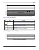
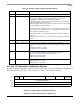
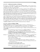
Figure 9-50. PCI Bus Interrupt Line Register
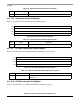
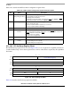
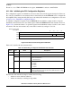
9.11.2.19 PCI Bus Interrupt Pin Register
Figure 9-51 and Table 9-38 describe the PCI bus interrupt pin register.
Figure 9-51. PCI Bus Interrupt Pin Register
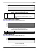
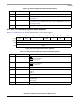
9.11.2.20 PCI Bus MIN GNT
Figure 9-52 and Table 9-39 describes the PCI bus MIN GNT register.
Figure 9-52. PCI Bus MIN GNT
7 0
Field IL
Reset 0000_0000
R/W R/W
Addr 0x3C
Table 9-37. PCI Bus Interrupt Line Register Description
Bits Name Description
7–0 Interrupt line Contains the interrupt routing information. Software can use this register to hold
information regarding which input of the system interrupt controller the INTA
signal is attached to. Values in this register are specific to the system
architecture.
7 0
Field IP
Reset 0000_0001
R/W R
Addr 0x3D
Table 9-38. PCI Bus Interrupt Pin Register Description
Bits Name Description
7–0 Interrupt Pin Indicates which interrupt pin the device (or function) uses (0x01 = INTA
).
7 0
Field MIN GNT
Reset 0000_0000
R/W R
Addr 0x3E