
User manual

Clocks and Power Control
MPC8260 PowerQUICC II Family Reference Manual, Rev. 2
Freescale Semiconductor 10-9
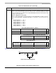
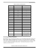
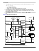
10.9 System Clock Mode Register (SCMR)
The system clock mode register (SCMR), shown in Figure 10-6, holds the parameters which determine the
output clock frequencies. To understand how these values interact, see Section 10.4, “Main PLL.”
Table 10-3 describes SCMR fields. Also, refer to Figure 10-1 to see these fields in the system PLL block
diagram.
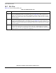
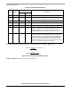
29 CLPD 0 Unaffected CPM low power disable.
0 Default. CPM does not enter low power mode when the core
enters low power mode.
1 CPM and SIU enter low power mode when the core does. This
may be useful for debug tools that use the assertion of QREQ
as an indication of breakpoint in the core.
Note: When the core is disabled, CLPD must be cleared.
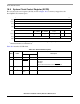
30–31 DFBRG 01 Unaffected Division factor of BRG_CLK relative to VCO_OUT (which is twice
the CPM clock). Defines the BRG_CLK frequency as shown in
Figure 10-1. Changing the value does not result in a loss of lock
condition.
00 Divide by 4
01 Divide by 16 (normal operation)
10 Divide by 64
11 Divide by 256
1
MPC8250, MPC8265, and MPC8266 only.
023 78 1112 15
Field — CORECNF
BUSDF CPMDF
Reset See Table 10-3.
R/W R
Addr 0x10C88
16 18 19 20 31
Field —
PLLDF PLLMF
Reset See Table 10-3.
R/W R
Addr 0x10C8A
Figure 10-6. System Clock Mode Register (SCMR)
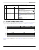
Table 10-2. SCCR Field Descriptions (continued)
Bits Name
Defaults
Description
POR Hard Reset