
User manual

Memory Controller
MPC8260 PowerQUICC II Family Reference Manual, Rev. 2
11-32 Freescale Semiconductor
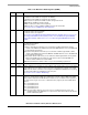
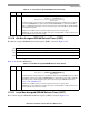
Table 11-16 describes LSRT fields.
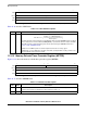
11.3.12 Memory Refresh Timer Prescaler Register (MPTPR)
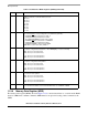
Figure 11-18 shows the memory refresh timer prescaler register (MPTPR).
Table 11-17 describes MPTPR fields.
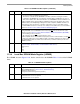
0 7
Field LSRT
Reset 0000_0000
R/W R/W
Addr 0x0x101A4
Figure 11-17. Local Bus-Assigned SDRAM Refresh Timer (LSRT)
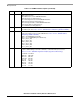
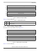
Table 11-16. LSRT Field Descriptions
Bits Name Description
0–7 LSRT Refresh timer period. Determines the timer period according to the following equation:
This timer generates refresh requests for all valid banks that selected a SDRAM machine assigned
to the local bus and is refresh enabled (LSDMR[RFEN] = 1). Each time the timer expires, all banks
that qualify generate a bank staggering auto refresh request using the SDRAM machine. See
Section 11.4.10, “SDRAM Refresh.”
Example: For a 25-MHz system clock and a required service rate of 15.6 µs, given
MPTPR[PTP] = 31, the LSRTvalue should be 11decimal. (12*32)/25 MHz = 15.36 µs, which is less
than the required service period of 15.6 µs.
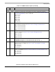
07815
Field PTP —
Reset undefined
R/W R/W
Addr 0x0x10184
Figure 11-18. Memory Refresh Timer Prescaler Register (MPTPR)
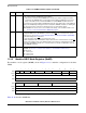
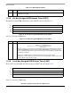
Table 11-17. MPTPR Field Descriptions
Bits Name Description
0–7 PTP Refresh timers prescaler. Determines the period of the memory refresh timers input clock. It divides
the
bus
clock. Prescaler clock frequency = Bus frequency / (PTP + 1).
8–15 — Reserved, should be cleared
T
imerPeriod
LSRT 1+()MPTPR PTP[]1+()×
Bus Frequency
---------------------------------------------------------------------------------------
⎝⎠
⎛⎞
=