
User manual

Memory Controller
MPC8260 PowerQUICC II Family Reference Manual, Rev. 2
11-40 Freescale Semiconductor
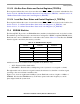
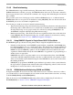
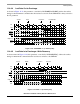
Figure 11-21. ACTTORW = 2 (2 Clock Cycles)
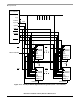
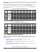
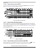
11.4.6.3 Column Address to First Data Out—CAS Latency
As seen in Figure 11-22, this parameter, controlled by P/LSDMR[CL], defines the timing for first read data
after a column address is sampled by the SDRAM.
Figure 11-22. CL = 2 (2 Clock Cycles)
CLK
ALE
CS
SDRAS
SDCAS
Rbz
WE
DQM
ACTIVATE
MA[0–11]
Command
ACTTORW = 2
DATA
D0 D1 D2 D3
WRITE
Command
Cbz
CLK
ALE
CSn
SDRAS
SDCAS
MA[0–11]
Row Column
WE
DQMn
Data
D0
D1
D2
D3
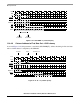
Activate Read First data out
CL = 2