
User manual
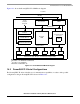
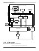

Communications Processor Module Overview
MPC8260 PowerQUICC II Family Reference Manual, Rev. 2
Freescale Semiconductor 14-11
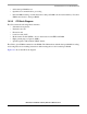
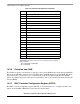
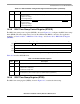
14.3.8 RISC Time-Stamp Control Register (RTSCR)
The RISC time-stamp control register (RTSCR), shown in Figure 14-4, configures the RISC time-stamp
timer (RTSR). The time-stamp timer is used by the ATM and the HDLC controllers. For application
examples, see Section 30.5.3, “ABR Flow Control Setup,” and Section 36.6, “HDLC Mode Register
(FPSMR).”
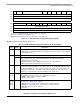
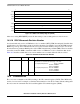
Table 14-4 describes RTSCR fields.
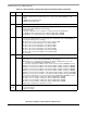
14.3.9 RISC Time-Stamp Register (RTSR)
The RISC time-stamp register (RTSR), shown in Figure 14-5, contains the time stamp.
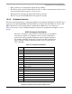
28 DEM12 Edge detect mode for DONE[1, 2] for IDMA[1, 2]. See Section 19.7.2, “DONEx.” DONE[1, 2]
asserts as follows:
0 High-to-low change
1 Low-to-high change
29 DEM34 Edge detect mode for DONE[3, 4]
for IDMA[3, 4]. See Section 19.7.2, “DONEx.” DONE[3, 4]
asserts as follows:
0 High-to-low change
1 Low-to-high change
0456 15
Field — RTE RTPS (Timer Prescale)
Reset 0000_0000_0000_0000
R/W R/W
Addr 0x0x119DC
Figure 14-4. RISC Time-Stamp Control Register (RTSCR)
Table 14-4. RTSCR Field Descriptions
Bits Name Description
0–4 — Reserved
5 RTE Time stamp enable.
0 Disable time-stamp timer.
1 Enable time-stamp timer.
6–15 RTPS Time-stamp timer pre-scale. Must be programmed to generate a 1-µs period input clock to the
time-stamp timer. (Time-stamp frequency = (CPM frequency)/(RTPS+2)
Table 14-3. RISC Controller Configuration Register Field Descriptions (continued)
Bits Name Description