
User manual


Communications Processor Module Overview
MPC8260 PowerQUICC II Family Reference Manual, Rev. 2
Freescale Semiconductor 14-17
14.4.2 Command Register Example
To perform a complete reset of the CP, the value 0x8001_0000 should be written to the CPCR. Following
this command, the CPCR returns the value 0x0000_0000 after two clocks.
14.4.3 Command Execution Latency
The worst-case command execution latency is 200 clocks and the typical command execution latency is
about 40 clocks.
14.5 Dual-Port RAM
The CPM static RAM (24 Kbyte on 0.29µm (HiP3) devices and 32 Kbyte on 0.25µm (HiP4) devices) is
shown in Figure 14-7.
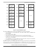
SET GROUP
ADDRESS
Set group address. Sets a bit in the hash table for the Ethernet logical group address recognition
function.
GCI ABORT
REQUEST
GCI abort request. The GCI receiver sends an abort request on the E-bit.
GCI TIMEOUT GCI time-out. The GCI performs the timeout function.
RESET BCS Reset block check sequence. Used in BISYNC mode to reset the block check sequence calculation.
MCC STOP
TRANSMIT
See Section 28.7, “MCC Commands.”
MCC STOP
RECEIVE
See Section 28.7, “MCC Commands.”
MCC RESET
1
MCC reset. Provides a hard reset to the MCC FIFOs. See Section 28.7, “MCC Commands.” To use
this command, software should execute the following sequence:
1 Disable the TDM by clearing the appropriate enable bit in SIxGMR[4-7] (See Table 14-4,
“SIxGMR Field Descriptions.”).
2 Issue the MCC RSET command.
3 Issue the INIT RX AND TX command.
4 Reprogram the specific MCC channel, global parameters, and any BDs that need to be updated.
5 Set the appropriate enable bit in SIxGMR[4-7]. (See Table 14-4, “SIxGMR Field Descriptions.”).
ATM TRANSMIT
2
See Section 30.14, “ATM Transmit Command.”
RANDOM NUMBER Generate a random number and put it in dual-port RAM; see RAND in Table 14-10.
1
Not available on .29µm (HiP3) Rev A.1 devices.
2
Not available on the MPC8250.
Table 14-8. Command Descriptions (continued)
Command Description