
User manual


Serial Interface with Time-Slot Assigner
MPC8260 PowerQUICC II Family Reference Manual, Rev. 2
Freescale Semiconductor 15-3
15.1 Features
Each SI has the following features:
• Can connect to four independent TDM channels. Each TDM can be one of the following:
— T1 or E1 line
— Integrated services digital network primary rate (PRI)
— An ISDN basic rate–interchip digital link (IDL) channel in up to four TDM channels—each
IDL channel requires support from a separate SCC
— ISDN basic rate–general circuit interface (GCI) in up to two TDM channels—each GCI
channel requires support from a separate SMC
— E3 or DS3 clear channel on TDMa only (parallel-nibble interface)
— User-defined interfaces
• Independent, programmable transmit and receive routing paths
• Independent transmit and receive frame syncs allowed
• Independent transmit and receive clocks allowed
• Selection of rising/falling clock edges for the frame sync and data bits
• Supports 1× and 2× input clocks (1 or 2 clocks per data bit)
• Selectable delay (0–3 bits) between frame sync and frame start
• Four programmable strobe outputs and four (2×) clock output pins
• 1- or 8-bit resolution in routing, masking, and strobe selection
• Supports frames up to 16,384 bits long
• Internal routing and strobe selection can be dynamically programmed
• Supports automatic echo and loopback mode for each TDM
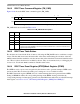
• Maximum TDM frequency is serial-dependent:
For the MCC route, the SI performs the following features:
• Up to 128 independent communication channels (64-Kbps per channel)
• Arbitrary mapping of any TDM time slots
• Can connect up to four independent TDM channels. Each TDM channel can support up to 128
channels (all four channels can support up to 128 channels together).
CPM Clock
7
— for MCCs
CPM Clock
6
— for FCCs transparent
— for all other serials
CPM Clock
3
— for FCCs HDLC
CPM Clock
4
— for FCCs HDLC nibble mode