
User manual

Serial Interface with Time-Slot Assigner
MPC8260 PowerQUICC II Family Reference Manual, Rev. 2
15-10 Freescale Semiconductor
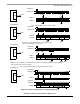
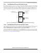
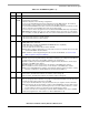
Figure 15-6. One TDM Channel with Shadow RAM for Dynamic Route Change
This configuration should be chosen when only one TDM is needed, but dynamic rerouting may be needed
on that TDM. Similarly, for two TDM channels, the number of SIx RAM entries are reduced for every
TDM channel programmed for shadow mode.
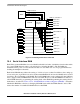
15.4.3 Programming SI
x
RAM Entries
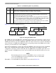
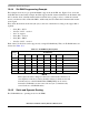
The programming of each entry in the SIx RAM determines the routing of the serial bits (or bit groups)
and the assertion of strobe outputs. If MCC is set, the entry refers to the corresponding MCC; otherwise,
it refers to other serial controllers. Figure 15-7 shows the entry fields for both cases.
The use of MCC slots is restricted for slots with lengths up to a single byte. For channels, that require more
than a single byte, superchannel or slot splitting is mandatory.
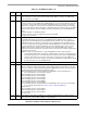
When MCC = 0, the SIx RAM entry fields function as described in Table 15-1.
0 1 2 3 4 5 6 7 10 11 13 14 15
Field MCC = 0 SWTR SSEL1 SSEL2 SSEL3 SSEL4 0 CSEL CNT BYT LST
MCC = 1 LOOP/ECHO SUPER MCSEL CNT BYT LST
R/W R/W
Addr See Chapter 3, “Memory Map.”
Figure 15-7. SI
x
RAM Entry Fields
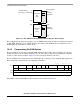
128 Entries
TXa
Route
Framing Signals
L1TCLKa
x
L1TSYNCa
x
SI
x
RAM Address:
128 Entries
RXa
Route
255
1279
1024
L1RCLKa
x
L1RSYNCa
x
1280
256
511
1535
(each entry is 16 Bits Wide)
0