
User manual

Serial Communications Controllers (SCCs)
MPC8260 PowerQUICC II Family Reference Manual, Rev. 2
20-8 Freescale Semiconductor
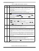
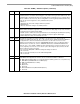
24–25 DIAG Diagnostic mode.
00 Normal operation, CTS
and CD are under automatic control. Data is received through RXD and
transmitted through TXD. The SCC uses modem signals to enable or disable transmission and
reception. These timings are shown in Section 20.3.5, “Controlling SCC Timing with RTS, CTS,
and CD.”
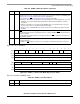
01 Local loopback mode. Transmitter output is connected internally to the receiver input, while the
receiver and the transmitter operate normally. The value on RXD is ignored. If enabled, data
appears on TXD, or the parallel I/O registers can be programmed to make TXD high. RTS
can
also be programmed to be disabled in the appropriate parallel I/O register. The transmitter and
receiver must share the same clock source, but separate CLK
x
pins can be used if connected
to the same external clock source.
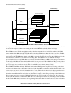
If external loopback is preferred, program DIAG for normal operation and externally connect TXD
and RXD. Then, physically connect the control signals (RTS
connected to CD, and CTS
grounded) or set the parallel I/O registers so CD
and CTS are permanently asserted to the SCC
by configuring the associated CTS
and CD pins as general-purpose I/O.
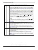
10 Automatic echo mode. The transmitter automatically resends received data bit-by-bit using the
Rx clock provided. The receiver operates normally and receives data if CD
is asserted. CTS is
ignored.
11 Loopback and echo mode. Loopback and echo operation occur simultaneously. CD
and CTS are
ignored. See the loopback bit description above for clocking requirements.
For TDM operation, the diagnostic mode is selected by SI
x
MR[SDM
x
]; see Section 15.5.2, “SI Mode
Registers (SIxMR).”
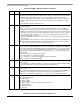
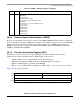
26 ENR Enable receive. Enables the receiver hardware state machine for this SCC.
0 The receiver is disabled and data in the Rx FIFO is lost. If ENR is cleared during reception, the
receiver aborts the current character.
1 The receiver is enabled.
ENR can be set or cleared, regardless of whether serial clocks are present. Section 20.3.7,
“Reconfiguring the SCCs,” describes how to disable/enable an SCC. Note that other tools, including
the
ENTER HUNT MODE and CLOSE RXBD commands and the E bit of the Rx BD, data provide the
capability to control the receiver.
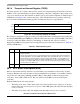
27 ENT Enable transmit. Enables the transmitter hardware state machine for this SCC.
0 The transmitter is disabled. If ENT is cleared during transmission, the current character is aborted
and TXD returns to the idle state. Data already in the Tx shift register is not sent.
1 The transmitter is enabled.
ENT can be set or cleared, regardless of whether serial clocks are present. Section 20.3.7,
“Reconfiguring the SCCs,” describes how to disable/enable an SCC. Note that other tools, such as
the
STOP TRANSMIT, GRACEFUL STOP TRANSMIT, and RESTART TRANSMIT commands, the freeze option
and CTS
flow control option in UART mode, and the R bit of the TxBD, also provide the capability to
control the transmitter.
Table 20-2. GSMR_L Field Descriptions (continued)
Bit Name Description