
User manual

SCC UART Mode
MPC8260 PowerQUICC II Family Reference Manual, Rev. 2
Freescale Semiconductor 21-11
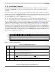
21.15 Handling Errors in the SCC UART Controller
The UART controller reports character reception and transmission error conditions via the BDs, the error
counters, and the SCCE. Modem interface lines can be monitored by the port C pins. Transmission errors
are described in Table 21-7.
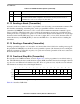
Reception errors are described in Table 21-8.
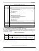
Table 21-6. DSR Fields Descriptions
Bit Name Description
0 — 0b0
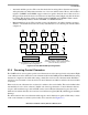
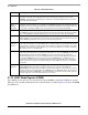
1–4 FSB Fractional stop bits. For 16× oversampling:
1111 Last transmitted stop bit 16/16. Default value after reset.
1110 Last transmitted stop bit 15/16.
…
1000 Last transmitted stop bit 9/16.
0xxx Invalid. Do not use.
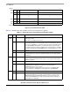
For 32× oversampling:
1111 Last transmitted stop bit 32/32. Default value after reset.
1110 Last transmitted stop bit 31/32.
…
0000 Last transmitted stop bit 17/32.
For 8× oversampling:
1111 Last transmitted stop bit 8/8. Default value after reset.
1110 Last transmitted stop bit 7/8.
1101 Last transmitted stop bit 6/8.
1100 Last transmitted stop bit 5/8.
10xx Invalid. Do not use.
0xxx Invalid. Do not use.
The UART receiver can always receive fractional stop bits. The next character’s start bit can begin
any time after the three middle samples have been taken.
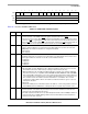
5–6 — 0b11
7–8 — 0b00
9–14 — 0b111111
15 — 0b0
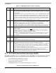
Table 21-7. Transmission Errors
Error Description
CTS
Lost
during
Character
Transmission
When CTS
negates during transmission, the channel stops after finishing the current character. The
CP sets TxBD[CT] and generates the TX interrupt if it is not masked. The channel resumes
transmission after the
RESTART TRANSMIT command is issued and CTS is asserted.
Note that if CTS
is used, the UART also offers an asynchronous flow control option that does not
generate an error. See the description of PSMR[FLC] in Table 21-9.