
User manual

SCC HDLC Mode
MPC8260 PowerQUICC II Family Reference Manual, Rev. 2
22-8 Freescale Semiconductor
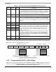
22.9 SCC HDLC Receive Buffer Descriptor (RxBD)
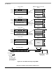
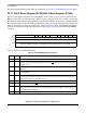
The CP uses the RxBD, shown in Figure 22-4, to report on data received for each buffer.
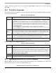
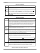
Table 22-7 describes HDLC RxBD status and control fields.
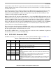
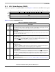
11 BRM HDLC bus RTS mode. Valid only if BUS = 1. Otherwise, it is ignored.
0Normal RTS
operation during HDLC bus mode. RTS is asserted on the first bit of the Tx frame
and negated after the first collision bit is received.
1 Special RTS
operation during HDLC bus mode. RTS is delayed by one bit with respect to the
normal case, which helps when the HDLC bus protocol is being run locally and sent over a
long-distance line at the same time. The one-bit delay allows RTS
to be used to enable the
transmission line buffers so that the electrical effects of collisions are not sent over the
transmission line.
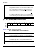
12 MFF Multiple frames in Tx FIFO. The receiver is not affected.
0 Normal operation. The Tx FIFO must never contain more than one HDLC frame. The CTS
lost
status is reported accurately on a per-frame basis.
1 The Tx FIFO can hold multiple frames, but lost CTS
may not be reported on the buffer/frame it
occurred on. This can improve performance of HDLC transmissions of small back-to-back frames
or when the number of flags between frames should be limited.
13–15 — Reserved, should be cleared.
0123456789101112131415
Offset + 0 E — WI LFCM — DE — LG NO AB CR OV CD
Offset + 2 Data Length
Offset + 4 Rx Buffer Pointer
Offset + 6
Figure 22-4. SCC HDLC Receive Buffer Descriptor (RxBD)
Table 22-7. SCC HDLC RxBD Status and Control Field Descriptions
Bits Name Description
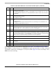
0 E Empty.
0 The buffer is full or reception stopped because of an error. The core can read or write to any fields
of this RxBD. The CP does not use this BD while E = 0.
1 The buffer is not full. The CP controls the BD and buffer. The core should not update the BD.
1 — Reserved, should be cleared.
2 W Wrap (last BD in the RxBD table).
0 Not the last BD in the table.
1 Last BD in the table. After this buffer is used, the CP receives incoming data using the BD pointed
to by RBASE. The number of BDs in this table are programmable and determined only by
RxBD[W] and overall space constraints of the dual-port RAM.
3 I Interrupt.
0 SCCE[RXB] is not set after this buffer is used; SCCE[RXF] is unaffected.
1 SCCE[RXB] or SCCE[RXF] is set when the SCC uses this buffer.
Table 22-6. PSMR HDLC Field Descriptions (continued)
Bits Name Description