
User manual

SCC HDLC Mode
MPC8260 PowerQUICC II Family Reference Manual, Rev. 2
22-20 Freescale Semiconductor
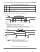
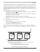
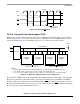
Figure 22-13. Nonsymmetrical Tx Clock Duty Cycle for Increased Performance
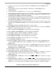
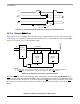
22.15.4 Delayed RTS Mode
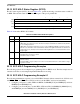
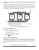
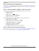
Figure 22-14 shows local HDLC bus controllers using a standard transmission line and a local bus. The
controllers do not communicate with each other but with a station on the transmission line; yet the HDLC
bus protocol controls access to the transmission line.
Figure 22-14. HDLC Bus Transmission Line Configuration
Normally, RTS goes active at the beginning of the opening flag’s first bit. Setting PSMR[BRM] delays
RTS
by one bit, which is useful when the HDLC bus connects multiple local stations to a transmission line.
If the transmission line driver has a one-bit delay, the delayed RTS
can be used to enable the output of the
line driver. As a result, the electrical effects of collisions are isolated locally. Figure 22-15 shows RTS
timing.
TCLK
CTS
(Input)
TXD
(Output)
CTS
sampled at three quarter point.
Collision detected when
TXD=1, but CTS
=0.
Local HDLC Bus
HDLC Bus
Controller
RXD CTS
TXD
A
HDLC Bus
Controller
RXD CTS
TXD
B
RTS
+ 3.3 V
R
NOTES:
1. The TXD pins of slave devices should be configured to open-drain in the port C parallel I/O port.
2. The RTS
pins of each HDLC bus controller are configured to delayed RTS mode.
RTS
Tx
Rx
EN
(1-Bit Delay)
Line Driver