
User manual

SCC BISYNC Mode
MPC8260 PowerQUICC II Family Reference Manual, Rev. 2
23-8 Freescale Semiconductor
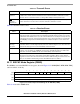
23.8 SCC BISYNC DLE Register (BDLE)
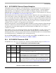
Seen in Figure 23-4, the BDLE register is used to define the BISYNC stripping and insertion of DLE
characters. When an underrun occurs while a message is being sent in transparent mode, the BISYNC
controller inserts DLE-SYNC pairs until the next buffer is available for transmission.
In transparent mode, the receiver discards any DLE character received and excludes it from the BCS if the
valid bit (BDLE[V]) is set. If the second character is SYNC, the controller discards it and excludes it from
the BCS. If it is a DLE, the controller writes it to the buffer and includes it in the BCS. If it is not a DLE
or SYNC, the controller examines the control character table and acts accordingly. If the character is not
in the table, the buffer is closed with the DLE follow character error bit set. If the valid bit is not set, the
receiver treats the character as a normal character. When using 7-bit characters with parity, the parity bit
should be included in the DLE register value.
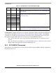
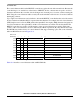
Table 23-6 describes BDLE fields.
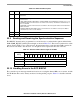
Table 23-5. BSYNC Field Descriptions
Bits Name Description
0 V Valid. If V = 1 and the receiver is not in hunt mode when a SYNC character is received, this character
is discarded.
1 DIS Disable BSYNC stripping
0 Normal mode.
1 BSYNC stripping disabled (BISYNC transparent mode only).
2–7 — All zeros
8–15 SYNC SYNC character
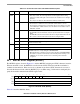
012345678 15
FieldVDIS000000 DLE
Reset Undefined
R/W R/W
Addr SCC Base + 0x40
Figure 23-4. BISYNC DLE (BDLE)