
User manual

Serial Management Controllers (SMCs)
MPC8260 PowerQUICC II Family Reference Manual, Rev. 2
27-4 Freescale Semiconductor
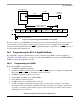
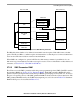
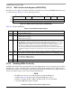
27.2.2 SMC Buffer Descriptor Operation
In UART and transparent modes, the SMC’s memory structure is like the SCC’s, except that
SMC-associated data is stored in buffers. Each buffer is referenced by a BD and organized in a BD table
located in the dual-port RAM. See Figure 27-3.
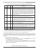
6 PEN Parity enable. (UART)
0No parity.
1 Parity is enabled for the transmitter and receiver as determined by the PM bit.
BS Byte sequence(transparent). Controls the byte transmission sequence if REVD is set for a character
length greater than 8 bits. Clear BS to maintain behavior compatibility with MC68360 QUICC.
0 Normal mode. This should be selected if the character length is not larger than 8 bits.
1 Transmit lower address byte first.
— Reserved, should be cleared. (GCI)
7 PM Parity mode. (UART)
0 Odd parity.
1 Even parity.
REVD Reverse data. (transparent)
0 Normal mode.
1 Reverse the character bit order. The msb is sent first.
C# SCIT channel number. (GCI)
0 SCIT channel 0
1 SCIT channel 1. Required for Siemens ARCOFI and SGS S/T chips.
8–9 — Reserved, should be cleared.
10–11 SM SMC mode.
00 GCI or SCIT support.
01 Reserved.
10 UART (must be selected for SMC UART operation).
11 Totally transparent operation.
12–13 DM Diagnostic mode.
00 Normal operation.
01 Local loopback mode.
10 Echo mode.
11 Reserved.
14 TEN SMC transmit enable.
0 SMC transmitter disabled.
1 SMC transmitter enabled.
15 REN SMC receive enable.
0 SMC receiver disabled.
1 SMC receiver enabled.
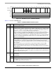
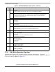
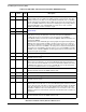
Table 27-1. SMCMR1/SMCMR2 Field Descriptions (continued)
Bits Name Description