
User manual

Serial Management Controllers (SMCs)
MPC8260 PowerQUICC II Family Reference Manual, Rev. 2
27-10 Freescale Semiconductor
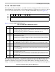
2. Issue an INIT TX AND RX PARAMETERS COMMAND to initialize transmit and receive parameters.
Make any additional SMCMR changes.
3. Set SMCMR[REN, TEN]. The SMC is now enabled with the new protocol.
27.2.5 Saving Power
When SMCMR[TEN, REN] are cleared, the SMC consumes little power.
27.2.6 Handling Interrupts in the SMC
Follow these steps to handle an interrupt in the SMC:
1. Once an interrupt occurs, read SMCE to identify the interrupt source. The SMCE bits are usually
cleared at this time.
2. Process the TxBD to reuse it if SMCE[TXB] is set. Extract data from the RxBD if SMCE[RXB]
is set. To send another buffer, set TxBD[R].
3. Execute the rfi instruction.
27.3 SMC in UART Mode
SMCs generally offer less functionality and performance in UART mode than do SCCs, which makes them
more suitable for simpler debug/monitor ports instead of full-featured UARTs. SMCs do not support the
following features in UART mode.
•RTS, CTS, and CD signals
• Receive and transmit sections clocked at different rates
• Fractional stop bits
• Built-in multidrop modes
• Freeze mode for implementing flow control
• Isochronous (1× clock) operation (A 16× clock is required for UART operation.)
• Interrupts on special control character reception
• Ability to transmit data on demand using the TODR
• SCCS register to determine idle status of the receive signal
• Other features for the SCCs as described in the GSMR
However, SMCs allow a data length of up to 14 bits; SCCs support up to 8 bits.
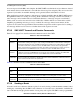
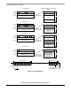
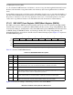
Figure 27-5. SMC UART Frame Format
SMCLK
SMTXD
16x
Start
Bit
Parity
Bit
(Optional)
5 to 14 Data Bits with the
Least Significant Bit First
1 or 2
Stop Bits
(not to scale)