
User manual


Serial Management Controllers (SMCs)
MPC8260 PowerQUICC II Family Reference Manual, Rev. 2
Freescale Semiconductor 27-31
27.5.2 Handling the GCI Monitor Channel
The following sections describe how the GCI monitor channel is handled.
27.5.2.1 SMC GCI Monitor Channel Transmission Process
Monitor channel 0 is used to exchange data with a layer 1 device (reading and writing internal registers
and transferring of the S and Q bits). Monitor channel 1 is used for programming and controlling
voice/data modules such as CODECs. The core writes the byte into the TxBD. The SMC sends the data
on the monitor channel and handles the A and E control bits according to the GCI monitor channel
protocol. The TIMEOUT command resolves deadlocks when errors in the A and E bit states occur on the
data line.
27.5.2.2 SMC GCI Monitor Channel Reception Process
The SMC receives data and handles the A and E control bits according to the GCI monitor channel
protocol. When the CP stores a received data byte in the SMC RxBD, a maskable interrupt is generated.
A
TRANSMIT ABORT REQUEST command causes the PowerQUICC II to send an abort request on the E bit.
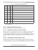
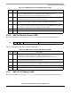
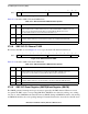
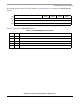
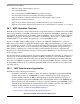
Table 27-17. SMC GCI Parameter RAM Memory Map
Offset
1
1
From the pointer value programmed in SMC
x
_BASE: SMC1_BASE at 0x87FC, SMC2_BASE at 0x88FC.
Name Width Description
0x00 M_RxBD Half
word
Monitor channel RxBD. See Section 27.5.5, “SMC GCI Monitor Channel RxBD.”
0x02 M_TxBD Half
word
Monitor channel TxBD. See Section 27.5.6, “SMC GCI Monitor Channel TxBD.”
0x04 CI_RxB
D
Half
word
C/I channel RxBD. See Section 27.5.7, “SMC GCI C/I Channel RxBD.”
0x06 CI_TxB
D
Half
word
C/I channel TxBD. See Section 27.5.8, “SMC GCI C/I Channel TxBD.”
0x08 RSTATE
2
2
RSTATE, M_RxD, M_TxD, CI_RxD, and CI_TxD do not need to be accessed by the user in normal operation, and are
reserved for RISC use only.
Word Rx/Tx Internal State
0x0C M_RxD
2
Half
word
Monitor Rx Data
0x0E M_TxD
2
Half
word
Monitor Tx Data
0x10 CI_RxD
2
Half
word
C/I Rx Data
0x12 CI_TxD
2
Half
word
C/I Tx Data