
User manual

Multi-Channel Controllers (MCCs)
MPC8260 PowerQUICC II Family Reference Manual, Rev. 2
28-10 Freescale Semiconductor
28.3.1.4 Internal Receiver State (RSTATE)—HDLC Mode
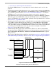
Internal receiver state (RSTATE) is a 4-byte register that provides transaction parameters associated with
SDMA channel accesses (like function code registers) and starts the receiver channel.
To start the channel the user must write 0xHH800000 to RSTATE, where HH is the RSTATE high byte
(see Figure 28-5). When the channel is active the CP changes the value of the 3 LSBs, hence these 3 bytes
must be masked if the user reads back the RSTATE.
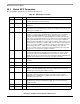
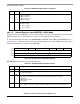
RSTATE high-byte fields are described in Table 28-5.
11–12 RQN Receive queue number. Specifies the receive interrupt queue number.
00 Queue number 0.
01 Queue number 1.
10 Queue number 2.
11 Queue number 3.
13–15 NOF Number of flags. NOF defines the minimum number of flags before frames:
000 At least 1 flag
001 At least 2 flags
....
111 At least 8 flags
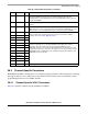
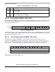
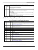
01234567
Field — GBL BO TC2 DTB BDB
Reset —
R/W R/W
Addr 0x20
Figure 28-5. Rx Internal State (RSTATE) High Byte
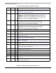
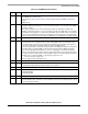
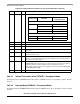
Table 28-5. RSTATE High-Byte Field Descriptions
Bits Name Description
0–1 — Reserved, should be cleared.
2
GBL
Global. Setting GLB activates snooping (only the 60X bus can be snooped, this parameter is ignored
for local bus transactions).
3–4
BO
Byte ordering. Set BO to select the required byte ordering for the buffer. If BO is changed on-the-fly,
it takes effect at the beginning of the next frame or at the beginning of the next BD.
00 Reserved
01 Munged little-endian.
1x Big-endian
5
TC2
Transfer code. Contains the transfer code value of TC[2], used during this SDMA channel memory
access. TC[0–1] is driven with a 0b11 to identify this SDMA channel access as a DMA-type access.
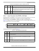
Table 28-4. CHAMR Field Descriptions (continued)
Bits Name Description