
User manual

Multi-Channel Controllers (MCCs)
MPC8260 PowerQUICC II Family Reference Manual, Rev. 2
Freescale Semiconductor 28-13
28.3.2.3 Channel Mode Register (CHAMR)—Transparent Mode
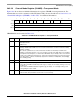
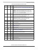
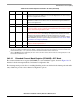
Figure 28-6 shows the user-initialized channel mode register, CHAMR, for transparent mode. For
channels that are used in conjunction with CES functionality, the user should refer to Section 28.3.3.2,
“Channel Mode Register (CHAMR)—AAL1 CES,” for additional information.
CHAMR fields are described in Table 28-4.
0 12345678910111213 15
Field MODE POL 1 1 EP RD SYNC — TS RQN —
Reset —
R/W R/W
Offset 0x1A
Figure 28-6. Channel Mode Register (CHAMR)—Transparent Mode
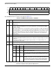
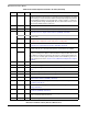
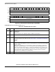
Table 28-7. CHAMR Field Descriptions—Transparent Mode
Bits Name Description
0 MODE Channel mode. Selects either HDLC or transparent mode.
0 Transparent mode.
1 HDLC mode
1 POL Enable polling. POL enables the transmitter to poll the TxBDs.
0 Polling is disabled (The CPM does not access the external bus to check the R bit in the TxBD).
1 Polling is enabled.
POL is used to optimize the use of the external bus. Software should always set POL at the
beginning of a transmit sequence of one or more frames. The CP clears POL when no more buffers
are ready in the transmit queue, i.e. when it finds a BD with R = 0 (for example, at the end of a frame
or at the end of a multi-frame transmission). To prevent a significant number of useless transactions
on the external bus, software should always prepare the new BD, or multiple BDs, and set BD[R]
before enabling polling.
2–3 0b11 Must be set.
4 EP Empty polarity and enable polling.
0 The E bit in the RxBD is handled in positive logic (1 = empty; 0 = not empty). Polling occurs only
if POL is set.
1 The E bit in the RxBD is handled in negative logic (0 = empty, 1 = not empty). Polling occurs
disregarding the value of POL.
5 RD 0 Normal bit order (transmit/receive the lsb of each octet first)
1 Reversed bit order (transmit/receive the msb of each octet first)