
User manual

Multi-Channel Controllers (MCCs)
MPC8260 PowerQUICC II Family Reference Manual, Rev. 2
28-24 Freescale Semiconductor
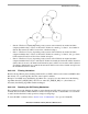
• For every JTRDelay an error flag is checked.
• If there is no error, decrement the counter SUERM by 1 (not below zero).
• If there is an error, increment the counter SUERM by D.
• If SUERM reaches T, the counter SUERM is cleared and a “signal unit error rate monitor” interrupt
is generated.
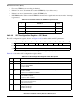
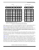
28.3.4.3 SS7 Configuration Register—SS7 Mode
The SS7 configuration register, shown on Figure 28-10 contains additional SS7 parameters.
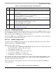
Table 28-13 describes SS7 configuration register fields.
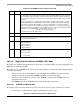
Table 28-12. Parameter Values for SUERM in Japanese SS7
Paramete
r
Definition Value
T Threshold 285
D Upcount 16
JTRDelay Length of interval (24ms) 0x2F
0 3 4 5 6 7 8 9 10 11 12 15
Field — AERM SUERM_DIS STD SF_DIS SU_FIL SEN_FIS O_ORN O_ITUT FISU_PAD
Reset
R/W R/W
Figure 28-10. SS7 Configuration Register (SS7_OPT)
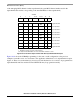
Table 28-13. SS7 Configuration Register Fields Description
Bits Name Description
0-3 — Reserved, should be cleared during initialization.
4 AERM Alignment error rate monitor enable. See Section 28.3.4.3.1, “AERM Implementation.”
0 Do not enable AERM.
1 Enable AERM.
5 SUERM_
DIS
Disable the SU error rate monitor. See Section 28.3.4.3.3, “Disabling SUERM.”
0 Enable SUERM.
1 Disables both SUERM and AERM.
6 STD Standard compliance
0ITU-T/ANSI compliant
1 Japanese SS7 compliant
7 SF_DIS Discard short frames (less than 5 octets)
0 Do not discard short frames.
1 Discard short frames.
8 SU_FIL SU Filtering
0 Disable SU filtering.
1 Enable SU filtering.