
User manual

ATM Controller and AAL0, AAL1, and AAL5
MPC8260 PowerQUICC II Family Reference Manual, Rev. 2
Freescale Semiconductor 30-25
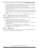
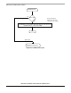
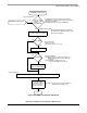
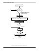
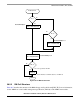
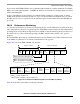
Figure 30-14. ABR Receive Flow
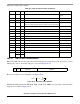
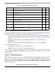
30.5.2 RM Cell Structure
Table 30-7 describes the structure of the RM cell supported by the PowerQUICC II. For more information,
see the ABR flow-control traffic management specification (TM 4.0) on the ATM Forum website.
B-RM Cells Rx
CI = 1
ACR = ACR-ACR×RDF
NI = 0
ACR = ACR+RIF×PCR
ACR = min(ACR,PCR)
ACR = min(ACR,ER)
ACR = max(ACR,MCR)
BN = 0
Unack = 0
EXIT
The source generate this RM
Unack = Number of F-RM in absence of B-RM = 0
Source End-Sys 5
Source End-Sys 1, 6
Source End-Sys 5, 6
Ye s
No
Ye s
No
No
Ye s