
User manual

ATM Controller and AAL0, AAL1, and AAL5
MPC8260 PowerQUICC II Family Reference Manual, Rev. 2
Freescale Semiconductor 30-45
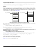
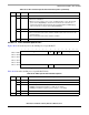
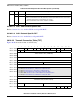
30.10.2.2.1 AAL5 Protocol-Specific RCT
Figure 30-26 shows the AAL5 protocol-specific area of an RCT entry.
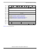
0x02 0 — Internal use only. Should be cleared.
1 INF (AAL5 only) Indicates the receiver state. Initialize to 0
0 In idle state.
1 In AAL5 frame reception state.
2–11 — Internal use only. Should be cleared.
12 ABRF (AAL5 only). Controls ABR flow.
0 ABR flow control is disabled.
1 ABR flow control is enabled.
13–15 AAL AAL type
000 AAL0—Reassembly with no adaptation layer
001 AAL1—ATM adaptation layer 1 protocol
010 AAL5—ATM adaptation layer 5 protocol
100 AAL2—ATM adaptation layer 2 protocol. Refer to Chapter 32, “ATM AAL2.”
101 AAL1_CES—Refer to Chapter 31, “ATM AAL1 Circuit Emulation Service.”
All others reserved.
0x04 — RxDBPTR Receive data buffer pointer. Holds real address of current position in the Rx buffer.
0x08 — Cell Time
Stamp
Used for reassembly time-out. Whenever a cell is received, the PowerQUICC II time
stamp timer is sampled and written to this field. See Section 14.3.8, “RISC
Time-Stamp Control Register (RTSCR).”
0x0C — RBD_Offset RxBD offset from RBD_BASE. Points to the channel’s current BD. User-initialized to
0; updated by the CP.
0x0E-0x
18
— Protocol-specific area.
0x1A — MRBLR Maximum receive buffer length. Used in both static and dynamic buffer allocation.
0x1C 0–1 — Reserved, should be cleared.
2–7 PMT Performance monitoring table. Points to one of the available 64 performance
monitoring tables. The starting address of the table is PMT_BASE+PMT × 32. Can be
changed on-the-fly.
8–15 RBD_BASE RxBD base. Points to the first BD in the channel’s RxBD table. The 8 most-significant
bits of the address are taken from BD_BASE_EXT in the parameter RAM. The four
least-significant bits of the address are taken as zeros.
0x1E 0–11
12–14 — Reserved, should be cleared.
15 PM Performance monitoring. Can be changed on-the-fly.
0 No performance monitoring for this VC.
1 Perform performance monitoring for this VC. Whenever a cell is received for this VC
the performance monitoring table that its code is written in the PMT field is updated.
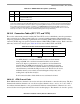
Table 30-16. RCT Field Descriptions (continued)
Offset Bits Name Description