
User manual

ATM Controller and AAL0, AAL1, and AAL5
MPC8260 PowerQUICC II Family Reference Manual, Rev. 2
30-46 Freescale Semiconductor
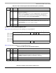
Table 30-17 describes AAL5 protocol specific RCT fields.
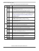
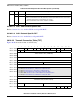
30.10.2.2.2 AAL5-ABR Protocol-Specific RCT
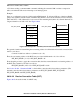
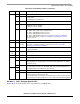
Figure 30-27 shows the AAL5-ABR protocol-specific area of an RCT entry.
0 15
Offset + 0x0E TML
Offset + 0x10 RX CRC
Offset + 0x12
Offset + 0x14 RBDCNT
Offset + 0x16 —
Offset + 0x18 — RXBM RXFM — BPOOL
Figure 30-26. AAL5 Protocol-Specific RCT
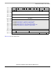
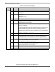
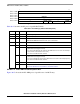
Table 30-17. RCT Settings (AAL5 Protocol-Specific)
Offset Bits Name Description
0x0E — TML Total message length. This field is used by the CP.
0x10 — RxCRC CRC32 temporary result.
0x14 — RBDCNT RxBD count. Indicates how may bytes remain in the current Rx buffer. RBDCNT is
initialized with MRBLR whenever the CP opens a new buffer.
0x16 — — Reserved, should be cleared.
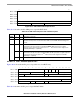
0x18 0–7 — Reserved, should be cleared.
8 RXBM Receive buffer interrupt mask. Determines whether the receive buffer event is
disabled. Can be changed on-the-fly.
0 The event is disabled for this channel. (The RXB event is not sent to the interrupt
queue when receive buffers are closed.)
1 The event is enabled for this channel.
9 RXFM Receive frame interrupt mask. Determines whether the receive frame event is
disabled. Can be changed on-the-fly.
0 The event is disabled for this channel. (RXF event is not sent to the interrupt queue.)
1 The event is enabled for this channel.
10–13 — Reserved, should be cleared.
14–15 BPOOL Buffer pool. Global buffer allocation mode only. Points to one of four free buffer pools.
See Section 30.10.5.2.4, “Free Buffer Pool Parameter Tables.”