
User manual

ATM Controller and AAL0, AAL1, and AAL5
MPC8260 PowerQUICC II Family Reference Manual, Rev. 2
Freescale Semiconductor 30-47
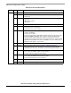
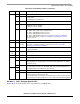
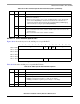
Table 30-18 describes AAL5-ABR protocol-specific RCT fields.
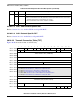
30.10.2.2.3 AAL1 Protocol-Specific RCT
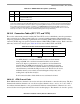
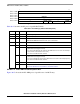
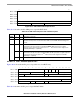
Figure 30-28 shows the AAL1 protocol-specific area of an RCT entry.
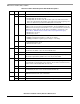
Table 30-19 describes AAL1 protocol-specific RCT fields.
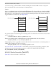
0 15
Offset + 0x0E AAL5 Protocol-Specific
Offset + 0x10
Offset + 0x12
Offset + 0x14
Offset + 0x16 PCR
Offset + 0x18 RDF RIF AAL5 Protocol-Specific
Figure 30-27. AAL5-ABR Protocol-Specific RCT
Table 30-18. ABR Protocol-Specific RCT Field Descriptions
Offset Bits Name Description
0x0E — — AAL5 protocol-specific
0x16 — PCR Peak cell rate. The peak number of cells per second of the current ABR channel. The ACR
(allowed cell rate) never exceeds this value. PCR uses the ATMF TM 4.0 floating-point
format.
0x18 0–3 RDF Rate decrease factor for the current ABR channel. Controls the decrease in cell
transmission rate upon receipt of a backward RM cell. RDF represents a negative
exponent of two, that is, the decrease factor = 2
-RDF
. The decrease factor ranges from
1/32768 (RDF=0xF) to 1 (RDF=0).
4–7 RIF Rate increase factor of the current ABR channel. Controls the increase in the cell
transmission rate upon receipt of a backward RM cell. RIF represents a negative exponent
of two, that is, the increase factor = 2
-RIF
. The increase factor ranges from 1/32768
(RIF=0xF) to 1 (RIF=0).
8–15 — AAL5 protocol-specific
0 1 2 3 4 5 6 7 8 9 10 11 12 13 14 15
Offset + 0x0E — PFM SRT INVE STF —
Offset + 0x10 SRTS_TMP — — SRTS_DEV
Offset + 0x12 — Valid Octet Size (VOS) SPV Structured Pointer (SP)
Offset + 0x14 RBDCNT
Offset + 0x16 — SN
Offset + 0x18 — SNEM — RXBM —
Figure 30-28. AAL1 Protocol-Specific RCT