
User manual

ATM Controller and AAL0, AAL1, and AAL5
MPC8260 PowerQUICC II Family Reference Manual, Rev. 2
Freescale Semiconductor 30-63
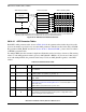
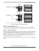
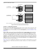
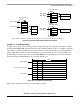
30.10.4 APC Data Structure
The APC data structure consists of three elements: the APC parameter tables for the PHY devices, the APC
priority table, and the APC scheduling tables. See Figure 30-38.
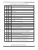
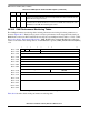
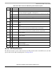
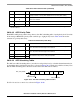
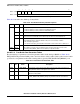
Table 30-28. OAM—Performance Monitoring Table Field Descriptions
Offset Bits Name Description
0x00 0 FMCE Enables FMC transmission. Initialize to 1.
1 TSTE FMC time stamp enable
0 The time stamp field of the FMC is coded with all 1’s.
1 The value of the time stamp timer is inserted into the time stamp field of the FMC.
2–4 — Reserved, should be cleared.
5–15 BLCKSIZE Performance monitoring block size ranging from 1 to 2,047 cells.
0x02 0–4 — Reserved, should be cleared.
5–15 TCC TX cell count. Used by the CP to count data cells sent. Initialize to zero.
0x04 — TUC1 Total user cell 1. Count of CLP = 1 user cells (modulo 65,536) sent. Should be cleared
initially.
0x06 — TUC0 Total user cell 0. Count of CLP = 0 user cells (modulo 65,536) sent. Should be cleared
initially.
0x08 — BEDC0+1-Tx Block error detection code 0+1–transmitted cells. Even parity over the payload of the
block of user cells sent since the last FMC. Should be cleared initially.
0x0A — BEDC0+1-RX Block error detection code 0+1–received cells. Even parity over the payload of the
block of user cells received since the last FMC. Should be cleared initially.
0x0C — TRCC1 Total received cell 1. Count of CLP = 1 user cells (modulo 65,536) received. Should
be cleared initially.
0x0E — TRCC0 Total received cell 0. Count of CLP = 0 user cells (modulo 65,536) received. Should
be cleared initially.
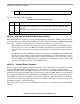
0x10 0–7 — Reserved, should be cleared.
8–15 SN-FMC Sequence number of the last FMC sent. Should be cleared initially.
0x12 — — Reserved, should be cleared.
0x14 — PMCH PM cell header. Holds the ATM cell header of the FMC, BRC to be inserted by the CP
into the Tx cell flow.
0x18–
0x1E
— — Reserved, should be cleared.