
User manual


ATM Controller and AAL0, AAL1, and AAL5
MPC8260 PowerQUICC II Family Reference Manual, Rev. 2
Freescale Semiconductor 30-71
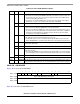
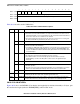
30.10.5.3 ATM Controller Buffers
Table 30-34 describes properties of the ATM receive and transmit buffers.
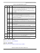
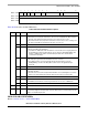
30.10.5.4 AAL5 RxBD
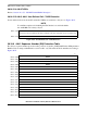
Figure 30-46 shows the AAL5 RxBD.
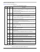
0x0A 0 BUSY The CP sets this bit when it tries to fetch buffer pointer with V bit clear.
FCCE[GBPB] is also set. Initialize to zero.
1 RLI Red-line interrupt. Set by the CP when it fetches a buffer pointer with I = 1.
FCCE[GRLI] is also set. Initialize to zero.
2–7 — Reserved, should be cleared.
8 EPD Early packet discard.
0 Normal operation.
1 AAL5 frames in progress are received, but new AAL5 frames associated with
this pool are discarded. Can be used to implement EPD under core control.
9–15 — Reserved, should be cleared.
0x0C — FBP_ENTRY Free buffer pool entry. Initialize with the first entry of the free buffer pool. Note that
FBP_ENTRY must be reinitialized with the entry pointed to by FBP_PTR when a
busy state occurs to reenable free buffer pool processing.
1
Offset from FBT_BASE+RCT[BPOOL] × 16
Table 30-34. Receive and Transmit Buffers
AAL
Receive Transmit
Size Alignment Size Alignment
AAL5 Multiple of 48 octets (except last buffer in frame) Burst-aligned
(recommended)
Any No
requirement
AAL1 At least 47 octets Burst-aligned
(recommended)
≥ 47 octets No
requirement
AAL0 52-64 octets. Burst-aligned 52–64
octets
No
requirement
01234567891011 12 13 1415
Offset + 0x00 E — WI LFCM — CLP CNG ABRT CPUU LNE CRE
Offset + 0x02 Data Length (DL)
Offset + 0x04 Rx Data Buffer Pointer (RXDBPTR)
Offset + 0x06
Figure 30-46. AAL5 RxBD
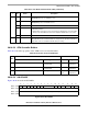
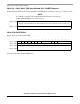
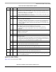
Table 30-33. Free Buffer Pool Parameter Table (continued)
Offset
1
Bits Name Description