LED Lighting Control Using the MC9S08AW60 Designer Reference Manual S08 Microcontrollers DRM093 Rev. 1 07/2007 freescale.
LED Lighting Control using the MC9S08AW60 Designer Reference Manual by: Dennis Lui, Ernest Chan Freescale Semiconductor, Inc. Hong Kong To provide the most up-to-date information, the revision of our documents on the World Wide Web is the most current. Your printed copy may be an earlier revision. To verify you have the latest information available, refer to: http://www.freescale.com The following revision history table summarizes changes contained in this document.
Revision History LED Lighting Control using the MC9S08AW60, Rev.
Table of Contents Chapter 1 Introduction 1.1 Introduction . . . . . . . . . . . . . . . . . . . . . . . . . . . . . . . . . . . . . . . . . . . . . 7 1.2 Features . . . . . . . . . . . . . . . . . . . . . . . . . . . . . . . . . . . . . . . . . . . . . . . 7 1.3 System Overview . . . . . . . . . . . . . . . . . . . . . . . . . . . . . . . . . . . . . . . . 8 1.4 MC9S08AW60 . . . . . . . . . . . . . . . . . . . . . . . . . . . . . . . . . . . . . . . . . . 8 Chapter 2 Hardware Description 2.1 Introduction .
Table of Contents 4.3.1 4.3.2 4.3.3 4.3.4 4.3.5 4.4 4.5 Demo 1 - Demonstration Display . . . . . . . . . . . . . . . . . . . . . . . . . 31 Demo 2 - Preset Colors Display . . . . . . . . . . . . . . . . . . . . . . . . . . 32 Demo 3 - Auto White Balance Control . . . . . . . . . . . . . . . . . . . . . 32 Demo 4 - PWM Output Frequency Control . . . . . . . . . . . . . . . . . . 32 Demo 5 - Full Manual Control . . . . . . . . . . . . . . . . . . . . . . . . . . . . 32 Program the MCU Flash . . . . . . . .
Chapter 1 Introduction 1.1 Introduction This manual describes a reference design of a multi-color LED lighting control solution by using the MC9S08AW60 Microcontroller.
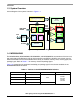
Introduction 1.3 System Overview A block diagram of the system is shown in Figure 1-1. Power Supply & Regulator AW60 Button Switch Detection KBI DC/DC Converter RGB PWM Red LEDs PWM Green LEDs To PC RS232 Interface SCI ADC Blue LEDs I/O Control GPIO Port Figure 1-1 . System Block Diagram 1.4 MC9S08AW60 The MC9S08AW60, MC9S08AW48, MC9S08AW32, and MC9S08AW16 are members of the low-cost, high-performance HCS08 family of 8-bit microcontroller units (MCUs).
MC9S08AW60 Table 1-2. Peripherals Available per Package Type Package Options Feature 64-Pin 48-Pin 44-Pin ADC 16-CH 8-CH 8-CH IIC Yes Yes Yes IRQ Yes Yes Yes KBI1 8 7 6 SCI1 Yes Yes Yes SCI2 Yes Yes Yes SPI1 Yes Yes Yes TPM1 6-CH 4-CH 4-CH TPM1CLK Yes No No TPM2 2-CH 2-CH 2-CH TPM2CLK Yes No No I/O Pins 54 38 34 LED Lighting Control using the MC9S08AW60, Rev.
Introduction LED Lighting Control using the MC9S08AW60, Rev.
Chapter 2 Hardware Description 2.1 Introduction The system consists of a MCU control board and a LED driving board. The MCU control board, DEMO9S08AW60LED, is one of the demonstration boards for the Freescale MC9S08AW60. This board allows easier developmet of code for LED control applications, architectural/entertainment lighting or LCD backlighting. The on-board serial interface allows you to control and monitor the system status via the RS232 serial port connection.
Hardware Description 2.
Development Support 2.4 Development Support Application development and debug for the MC9S08AW60 is supported through a 6-pin BDM header (CON8). The pinout is as follows: Table 2-1. BDM Connector (CON8) Pinout BKGD 1 2 GND NC 3 4 RESET NC 5 6 VDD 2.5 Power The DEMO9S08AW60LED is powered externally through the barrel connector CON2. This connector is a 2.5 mm, center positive connector. Voltage supplied through this connector should be positive 12 volts DC.
Hardware Description 2.9 User Options The DEMO9S08AW60LED includes various input and output devices to assist in application development. These devices include four pushbutton switches, four LEDs, and an operational amplifier with RC filter connected at each ADC input channel for signal amplification and filtering. 2.9.1 Pushbutton Switches Four pushbutton switches provide momentary active low input for user applications. The table below describes the pushbutton switch connections. Table 2-3.
User Options 2.9.4 Other I/O Connectors One user assignable and eight pre-defined I/O connectors are available to help users connect the board into their target system. Table 2-5. IIC Port CON5 Signal Name Remarks Pin 1 NC Install a zero ohm resistor in the R14 footprint to connect VDD Pin 2 SCL Connected to MCU PTC0/SCL1 10 kΩ pullup to VDD Pin 3 SDA Connected to MCU PTC1/SDA1 10 kΩ pullup to VDD Pin 4 GND — Table 2-6.
Hardware Description Table 2-8. PWM Port CON4 Signal Name Remarks Pin 1 PWM R Connected to MCU PTF0/TPM1CH2 Pin 2 PWM G Connected to MCU PTF1/TPM1CH3 Pin 3 PWM B Connected to MCU PTE2/TPM1CH0 Pin 4 GND — Table 2-9.
User Options Table 2-11.
Hardware Description Table 2-13. User Assignable Input (Continued) CON13 Signal Name Remarks Pin 7 DCDC_CTL1 Connected to MCU PTF4/TPM2CH0 Pin 8 DCDC_CTL2 Connected to MCU PTF5/TPM2CH1 Pin 9 DCDC_CTL3 Connected to MCU PTE3/TPM1CH1 Pin 10 GND — 2.10 LED Driving Board In general, LEDs have a nonlinear I-V behavior and current limitation is required to prevent the power dissipation to exceed a maximum limit. Therefore, the ideal source for LED driving is a constant current source.
LED Driver Design Procedures Vout = 30V Vin = 12V R-Channel PWM VLED x 8 8 LEDs 8 LEDs 8 LEDs DC-to-DC Boost Converter (MC34063) Driver R G-Channel PWM ILED = 50mA Driver G B-Channel PWM VDROP VREF Rs VRS Driver B Figure 2-3. DC-to-DC Boost Converter and Linear LED Driver Eight pieces of 3-in-1 RGB LED chips connected in series are used to form the multi-color light source. The LED chips are arranged in 2 x 4 format and each RGB LED string is driven by a separated constant current source.
Hardware Description 2.11.2 Current Sense Resistor The value of the current sense resistor RS is determined by two factors: power dissipation on RS and the reference level VREF for operational amplifier non-inverting input. Smaller RS reduces power dissipation, but the detection of a feedback signal in operational amplifier is more difficult. The voltage VRS across the current sense resistor RS is directly proportional to the current ILED through LED.
LED Driver Design Procedures Figure 2-4. Equations for Boost Converter Vsat = Saturation voltage of the output switch. VF = Forward voltage drop of the output rectifier. Vin - Nominal input voltage. Vout - Desired output voltage. Iout - Desired output current. fmin - Minimum desired output switching frequency. Vripple(pp) - Desired peak-to-peak output ripple voltage. For further information, refer to On Semiconductor’s datasheet. LED Lighting Control using the MC9S08AW60, Rev.
Hardware Description LED Lighting Control using the MC9S08AW60, Rev.
Chapter 3 Firmware Description 3.1 Introduction The MCU firmware in this LED lighting control design is responsible for: • Controlling timer channels for the RGB LED color PWM output • Communicating with the host PC for receiving command and data input/output • Operating as a standalone LED box through on board buttons Figure 3-1 and Figure 3-2 shows the firmware flow. The LED box can operate in PC control operation mode or standalone operation mode.
Firmware Description PWM value input to one channel Auto White balance? No Yes Prompt for green channel PWM input and calculate the two remaining channels’ PWM values according to existing color temperature Get the other two channel values from user input Adjust PWM width in next PWM cycle Figure 3-2. Firmware Flow: PWM Adjustment 3.2 PC Control Mode Every time the MCU is powered up, the firmware detects the status of SW1.
PC Control Mode Figure 3-3. User Interface Menu When the MCU receives a control command or PWM input data from the PC, the firmware interprets the information to take the corresponding actions. It may update the output PWM values in next PWM duty or delivery of the corresponding LED control parameter back to the PC. Three timer channels in the timer 1 module are configured to edge-aligned PWM operation mode. This generates the PWM signals for the RGB color channels.
Firmware Description 3.3 Standalone Mode When the LED box is powered up with SW1 being pressed, it enters standalone mode. When compared to the PC control mode, this standalone mode can act as a quick and simple demo that does not require a host PC. The control of the LED light box can be done through the onboard buttons. However, the PC control mode can have more control on the PWM output.
Firmware Files 3.4 Firmware Files Below is a list of the C files in the firmware Main.c • • • Programs entry point and determination of operation mode, i.e. PC control mode or standalone operation mode System initialization Common functions used in different firmware modules Menu.c • • Takes care of high level user interface communication with the PC host. Interprets the received PC commands or data and initiate the corresponding action.
Firmware Description LED Lighting Control using the MC9S08AW60, Rev.
Chapter 4 Demo Setup 4.1 Introduction This section shows how to connect the DEMO9S08AW60LED board to your PC, run the demo program, and how to program the board with the source code. The source code can be download from the Freescale website. 4.2 Hardware and Software Setup The DEMO9S08AW60LED is shipped with the demo program stored in on-chip flash memory. Use Figure 2-2 as a guide to do the setup. 4.2.1 Hardware Setup 1.
Demo Setup Figure 4-1. Echo Typed Characters Setting LED Lighting Control using the MC9S08AW60, Rev.
Demo Examples Figure 4-2. LED Control Menu NOTE Make sure the HyperTerminal window is selected all the time by moving the mouse pointer inside the window and clicking the left mouse button (the top color bar of the terminal window is then blue instead of grey). Otherwise, no function key command is sent to the LED lightbox. 4.3 Demo Examples Several examples are given here on showing how to use the LED box under the PC control. 4.3.1 Demo 1 - Demonstration Display 1.
Demo Setup 4.3.2 Demo 2 - Preset Colors Display 1. Press the tab key in the PC keyboard. 2. The output is switched to another preset color after the tab key has been pressed each time. NOTE You can adjust the output color any time through the control menu. 4.3.3 Demo 3 - Auto White Balance Control 1. 2. 3. 4. Press F until PWM frequency is set to 120 Hz. Press W to toggle to AUTO white balance control. Type 2000 at line of input green. The green PWM output value should then show 2000.
Program the MCU Flash NOTE Max PWM input range is decreased when setting to a higher PWM frequency. With the same PWM values, increasing frequency (i.e. shorter period) increases brightness because the PWM on-duty increases. When typing HEX PWM input values, use only capital letters for the input of A–F. 4.4 Program the MCU Flash The DEMO9S08AW60LED board allows you to program the MCU flash and debug applications via the BDM connection. 1.
Demo Setup Repeat the PC software setup procedures again. 3. Control menu contents are not correct Make sure the COM port selection is correct. Check the Port Settings again and make sure the configurations are correct. 4. User input does not be detected correctly Make sure the HyperTerminal Window is being selected all the time. When typing HEX PWM input values, use ONLY CAPITAL letter for the input of A–F. Use the + or − keys from the main keyboard area instead of those near the NUM lock key pad.
Appendix A Schematics LED Lighting Control using the MC9S08AW60, Rev.
LED Lighting Control using the MC9S08AW60, Rev.
LED Lighting Control using the MC9S08AW60, Rev.
LED Lighting Control using the MC9S08AW60, Rev.
LED Lighting Control using the MC9S08AW60, Rev.
LED Lighting Control using the MC9S08AW60, Rev.
Appendix B Bill of Materials LED Lighting Control using the MC9S08AW60, Rev.
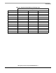
Table 4-1 BOM for AW60 Control Board Part Description SMD RESISTOR SMD RESISTOR Quantity Value 510 6 820 1 SMD RESISTOR Designators R1 R3-7 R2 R8 R9 R11 R14-16 R28 R30 R34 R36 R40 R42 R46 R48 R52 R54 R58 R60 R64 R66 R70 R72 R74-76 R32 R12 R37-38 R17-18 R43-44 R49-50 R22 R55-56 R61-62 R25-26 R67-68 R13 R73 R31 R35 R23 R59 R24 R47 R65 R20 R41 R71 R21 R29 R10 R53 R19 R69 R27 R63 R51 R57 R39 R45 R33 C4 C6-8 C12-14 C16 C22 C27 C3 C9-10 C33 C18-20 C15 C23-25 C17 C28-32 C34-36 C11 C21 C26 C2 C5 C1 CON8 25 ope
Table 4-2 BOM for LED Driving Board Part Description SMD RESISTOR SMD RESISTOR SMD RESISTOR SMD RESISTOR SMD RESISTOR SMD RESISTOR SMD RESISTOR SMD RESISTOR SMD RESISTOR Quantity 5 1 1 1 1 2 1 1 1 Value 0 52K 2K2 0.
LED Lighting Control using the MC9S08AW60, Rev.
How to Reach Us: Home Page: www.freescale.com E-mail: support@freescale.com USA/Europe or Locations Not Listed: Freescale Semiconductor Technical Information Center, CH370 1300 N. Alma School Road Chandler, Arizona 85224 +1-800-521-6274 or +1-480-768-2130 support@freescale.