
User's Manual
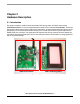

User Options
LED Lighting Control using the MC9S08AW60, Rev. 1
Freescale Semiconductor 15
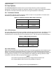
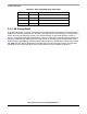
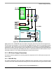
2.9.4 Other I/O Connectors
One user assignable and eight pre-defined I/O connectors are available to help users connect the board
into their target system.
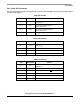
Table 2-5. IIC Port
CON5 Signal Name Remarks
Pin 1 NC
Install a zero ohm resistor in the R14 footprint to
connect V
DD
Pin 2 SCL
Connected to MCU PTC0/SCL1
10 kΩ pullup to V
DD
Pin 3 SDA
Connected to MCU PTC1/SDA1
10 kΩ pullup to V
DD
Pin 4 GND —
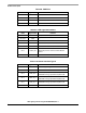
Table 2-6. SCI Port
CON6 Signal Name Remarks
Pin 1 NC
Install a zero ohm resistor in the R15 footprint to
connect V
DD
Pin 2 SCI_TX Connected to MCU PTE0/TXD1
Pin 3 SCI_RX Connected to MCU PTE1/RXD1
Pin 4 GND —
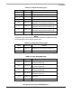
Table 2-7. SPI Port
CON7 Signal Name Remarks
Pin 1 NC
Install a zero ohm resistor in the R16 footprint to
connect V
DD
Pin 2 GND —
Pin 3 SPI_SS Connected to MCU PTE4/SS1
Pin 4 SPI_MISO Connected to MCU PTE5/MISO1
Pin 5 SPI_MOSI Connected to MCU PTE6/MOSI1
Pin 6 SPI_SCK Connected to MCU PTE7/SPSCK1