
User's Manual


LED Lighting Control using the MC9S08AW60, Rev. 1
Freescale Semiconductor 29
Chapter 4
Demo Setup
4.1 Introduction
This section shows how to connect the DEMO9S08AW60LED board to your PC, run the demo program,
and how to program the board with the source code. The source code can be download from the
Freescale website.
4.2 Hardware and Software Setup
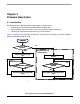
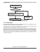
The DEMO9S08AW60LED is shipped with the demo program stored in on-chip flash memory. Use
Figure 2-2 as a guide to do the setup.
4.2.1 Hardware Setup
1. Check the jumper setting and make sure jumper JP1 on DEMO9S08AW60LED board is set to the
5V (2-3) position.
2. Connect the 2x5 pin ribbon flat cable at LED light box to connector CON3 on
DEMO9S08AW60LED board.
3. Connect a serial cable to the PC or notebook and then to the DEMO9S08AW60LED board.
4. Power up the demo through the DC jack connector CON1 on DEMO9S08AW60LED board. The
supply voltage is 12V DC and LED D5 should be on.
5. Press SW5 to reset the MCU. The LED light box demo enters PC control mode. (Make sure SW1
is not pressed during reset.)
4.2.2 PC Software Setup
1. Open up a terminal window from within Windows XP by clicking on Start → All Programs →
Accessories → Communications → HyperTerminal
2. Give your terminal connection a name (such as AW60_Control) and click the OK button.
3. In the Connect using pulldown, select the COM port you connected your serial cable to, and click
the OK button.
4. In the Port Settings window, click the OK button after entering the following settings:
Bits per second: 9600
Data bits: 8
Parity: None
Stop bits: 1
Flow control: None
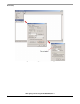
5. Make sure Echo typed characters locally is NOT selected under the ASCII Setup pop-up menu,
see Figure 4-1.
6. After configuring HyperTerminal, the LED Control Menu screen appears as shown in Figure 4-2.