
User's Manual


Program the MCU Flash
LED Lighting Control using the MC9S08AW60, Rev. 1
Freescale Semiconductor 33
NOTE
Max PWM input range is decreased when setting to a higher PWM
frequency. With the same PWM values, increasing frequency (i.e. shorter
period) increases brightness because the PWM on-duty increases.
When typing HEX PWM input values, use only capital letters for the input
of A–F.
4.4 Program the MCU Flash
The DEMO9S08AW60LED board allows you to program the MCU flash and debug applications via the
BDM connection.
1. Download the source code file from Freescale web site, save it to your PC, and extract the files to
a working directory on your machine.
2. Open CodeWarrior HC(S)08 v5.1 and open the LED_box.mcp project file.
3. Open main.c in the sources folder by clicking the plus sign next to the sources folder and then
double clicking on main.c. This is the application code.
4. Connect the BDM cable from your development tools to the DEMO9S08AW60LED board (CON8).
5. Connect a serial cable to the PC and then to the DEMO9S08AW60LED board.
6. Power up the demo through the DC jack connector CON1 on DEMO9S08AW60LED board.
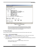
7. Open up a terminal window from within Windows XP by clicking on Start → All Programs →
Accessories → Communications → HyperTerminal
8. Give your terminal connection a name (such as AW60_Control) and click the OK button.
9. In the Connect using pulldown, select the COM port you connected your serial cable to, and click
the OK button.
10. In the Port Settings window, click the OK button after entering the following settings:
Bits per second: 9600
Data bits: 8
Parity: None
Stop bits: 1
Flow control: None.
11. In the Freescale CodeWarrior window, click on Debug under Project in the menu bar or press F5.
The True-Time Simulator and Real-Time Debugger interface window appears.
12. When the ICD Connection Assistant appears, click the Connect button.
13. When the Erase and Program Flash window appears, click the yes button.
14. The CPROGHCS08 Programmer window should close after the MCU flash is programmed. To run
the source code, click on Start/Continue under Run in the menu bar or click the green arrow.
4.5 Troubleshooting
1. V
DD
LED does not turn on
Make sure jumper JP1 is set to the 5V (2-3) position.
2. The light box does not display any color
Make sure the 2x5 pin ribbon flat cable at LED light box is installed properly to the
DEMO9S08AW60LED board.