Variable Speed DC Fan Control using the MC9RS08KA2 Designer Reference Manual RS08 Microcontrollers DRM079 Rev. 0 5/2006 freescale.
Variable Speed DC Fan Control using the MC9RS08KA2 Designer Reference Manual by: Vincent Ko Freescale Semiconductor, Inc. Hong Kong To provide the most up-to-date information, the revision of our documents on the World Wide Web will be the most current. Your printed copy may be an earlier revision. To verify that you have the latest information available, refer to http://www.freescale.com The following revision history table summarizes changes contained in this document.
Revision History Variable Speed DC Fan Control using the MC9RS08KA2, Rev.
Table of Contents Chapter 1 Introduction 1.1 1.2 1.3 1.4 Introduction . . . . . . . . . . . . . . . . . . . . . . . . . . . . . . . . . . . . . . . . . . . . . . . . . . . . . . . . . . . . . . . . . Freescale’s New Generation Ultra Low Cost MCU . . . . . . . . . . . . . . . . . . . . . . . . . . . . . . . . . . . DC Fan Reference Design Targets . . . . . . . . . . . . . . . . . . . . . . . . . . . . . . . . . . . . . . . . . . . . . . . Bi-Phase BLDC Motor . . . . . . . . . . . . . . . . . . . . . . . . .
Table of Contents Variable Speed DC Fan Control using the MC9RS08KA2, Rev.
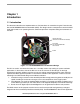
Chapter 1 Introduction 1.1 Introduction This document describes the implementation of a DC brushless fan controller using the Freescale ultra low cost MC9RS08KA2 8-bit microcontroller (MCU). The design contains a temperature sensor the MCU reads with control on fan speed against the ambient temperature. Complete coding and schematic are included. VARIABLE RESISTOR (TO EMULATE A TEMPERATURE SENSOR) MC9RS08KA2 MCU IN 8-PIN NARROW BODY SOIC PACKAGE BUZZER Figure 1-1.
Introduction 1.2 Freescale’s New Generation Ultra Low Cost MCU The MC9RS08KA2 microcontroller unit (MCU) is an extremely low cost, small pin count device for home appliances, toys, and small geometry applications, such as a DC fan controller. This device is composed of standard on-chip modules including a very small and highly efficient RS08 CPU core, 62 bytes RAM, 2K bytes FLASH, an 8-bit modulo timer, keyboard interrupt, and analog comparator. The device is available in small 6- and 8-pin packages.
Bi-Phase BLDC Motor 1.4 Bi-Phase BLDC Motor The brushless DC motor (BLDC) design for DC fan is commonly consist of a permanent magnet attached on the rotor and the stator phase coil windings are mounted on the motor shaft as illustrated in Figure 1-2. The BLDC has no brushes on the rotor and the commutation is performed electronically at certain rotor positions. Hall Effect Sensor Stator Coil Axle Fan Hub Permanent Magnets Figure 1-2.
Introduction Variable Speed DC Fan Control using the MC9RS08KA2, Rev.
Commutation Chapter 2 Motor Control 2.1 Commutation The typical bi-phase BLDC has one pole-pair per phase. Each commutation rotates the rotor by 90 degrees and four commutation steps complete a mechanical revolution. Each pole-pair is implemented by two coils, with four coils in total for a bi-phase motor.
Motor Control 2.3 Commutation Waveforms In general, in a bi-phase motor design, alternate coils are tied together and give a single connection to the driver. In this design, the driver connection for coil A and coil C is called L1 (see Figure 2-1). Similarly, the driver connection for coil B and coil D is called L2. Driving to either of the connections will energize a coil-pair. The commutation waveform is shown in Figure 2-2. The coil driving period is aligned with the Hall sensor output.
Motor Startup Dramatic changes in the dead-time value will cause the motor to stall. In this design a software loop in the MCU will control the dead-time variation. Even with the dramatic change in the temperature sensor reading, the software loop will only allow the dead-time to change to the new value gradually. 2.5 Motor Startup In this DC fan application, it is desirable to only allow the motor to operate in an uni-direction, such that the airflow to the target system will always be in one direction.
Motor Control Variable Speed DC Fan Control using the MC9RS08KA2, Rev.
Block Diagram Chapter 3 Implementation 3.1 Block Diagram The block diagram of the DC fan design is illustrated in Figure 3-1. A 12V low cost bi-phase BLDC motor is used in this application. The MCU performs alternate outputs to the two NPN transistors that drive the motor coils. Open drain output Hall sensor is required and positioned close the rotor.
Implementation Hall sensor output is connected to the MCU’s GPIO port, PTA2, which has a programmable edge trigger keyboard interrupt (KBI). The programmable edge trigger feature provides an effective way to monitor the Hall sensor signal. As mentioned in the previous section, the direction of rotation can be detected by the polarity of the Hall sensor output edge. Monitoring the signal edge is achieved by altering the KBI edge trigger polarity for each commutation step.
Control Loop START Continuously monitor the hall sensor output TargetPWMPeriod = Longest ActualPWMPeriod = Longest Energize L1 / L2 Drive L1 Start Timer Read Temp. Sensor Hall Edge? De-energized coils = DeadTime N Timeout? Y Y Stop Timer Record DriveTime Drive L2 N De-energize Coils Read Temp. Sensor Sound Buzzer De-energize Coils Fault condition detected.
Implementation 3.4 Temperature Sensor Measurement The temperature sensor measurement is performed based on the methodology of an emulated ADC described in the application note, AN3266 “Getting Started with RS08”. VDD ON-CHIP COMPARATOR R 4k7 + VDD 7k5 – C 22nF MCU BOUNDARY TEMP SENSOR 10k Figure 3-3. Emulated ADC Schematic The schematic of the emulated ADC in this application is shown in Figure 3-3. The ADC input is the temperature sensor resistor ladder.
Temperature Sensor Measurement Table 3-2. RC Charging Profile Against Timer Count Time (µs) Voltage across the Temperature Sensor (V) ADC Readout (Timer Count) 0 0 0 2 0.10 1 4 0.19 2 6 0.28 3 and so on... 86 2.82 43 88 2.87 44 90 2.91 45 and so on... 126 3.52 63 Table 3-2 shows the entire dynamic range of the temperature sensor voltage can be covered by about 44 timer counts.
Implementation As described in the previous section the overall dead-time duration should be deterministic, the double WAIT statements in the subroutine can ensure the execution time to be mostly constant. When the MCU is woken up from the first WAIT (which is normally triggered by the comparator), the timer counter value is captured and the MCU is then returned to WAIT mode until the timer is overflowed.
Temperature Sensor Measurement Table 3-3. Temperature Conversion Table Temperature (°C) Channel Resistance (kΩ) (from sensor data sheet) Voltage across Sensor (V) Predefined Motor Speed (rpm) Target PWM Period (Timer Counts(1)) 25 or below 10 2.86 1000 232 30 – 34 8.082 2.59 1200 193 35 – 39 6.577 2.34 1400 165 40 – 44 5.387 2.09 1600 144 45 – 49 4.441 1.86 1800 128 50 – 54 3.683 1.65 2000 115 55 – 59 3.024 1.44 2200 105 60 – 64 2.53 1.26 2400 96 65 – 69 2.
Implementation Variable Speed DC Fan Control using the MC9RS08KA2, Rev.
C2 1 2 3 4 5 12V L1 L2 GND HALL GND 2 BLDC FAN CONNECTOR COM L1 L2 GND HALL P3 2u2F/25V 1 12V 1 2 GND 12V 1 GND 2 1 5V 10K R2 LL4148 D1 12V_IN 2 1 2u2F/25V C3 2u2F/25V C4 2 2 1 GND Z1 2 1 1 2 FMMT491A Q1 3 2 FMMT491A Q2 3 ZMM5231B 1 GND 220 1 2 R1 C6 1uF/10V LL4148 LL4148 P1 1 2 1 12V GND 1 2 1 1 D2 D3 Freescale Semiconductor 2 5V 1K5 R7 1K5 R6 2 2 DC1 0.
Implementation Variable Speed DC Fan Control using the MC9RS08KA2, Rev.
Temperature Sensor Measurement Appendix B. Program Listing ;************************************************************** ; ; (c) copyright Freescale Semiconductor.
Implementation MTIM_TCLK_FALLING MTIM_TCLK_RISING equ equ $20 $30 ;========================================================================= ; ACMP Definition ;========================================================================= ACMP_OUTPUT_FALLING equ $00 ACMP_OUTPUT_RAISING equ $01 ACMP_OUTPUT_BOTH equ $03 ;========================================================================= ; RTI Definition ;========================================================================= RTI_DISABLE equ $00 RTI_8M
Temperature Sensor Measurement TargetPeriod ActualPeriod DriveTime SensorReading MotorRunning ds.b ds.b ds.b ds.b ds.
Implementation sta sta KBIES KBIPE ;HALL rising Edge Trigger ;KBI Enable ;------------------------------------------------------;Config MTIM ; ;Timer prescalar=256 -> Timer clk = 16kHz ;Bus = 4MHz ;Max OF period = 16.
Temperature Sensor Measurement ;5) Read Temp Sensor Again bsr ReadSensor ; Read Sensor value ;6) Dead time control StartTimer ;7) During the dead time, update dead time period every 128ms brclr SRTISC_RTIF, MAP_ADDR_6(SRTISC), UpdateLater; Update PWM duty cycle jsr TableLookup UpdateLater: lda ActualPeriod sub TargetPeriod ; Actual-Target blo IncPeriod beq WaitAgain ; if same, Fan speed reach target then exit DecPeriod: lda cmp blo dec bra DeadTime #MinDeadTime WaitAgain DeadTime WaitAgain IncPeriod: l
Implementation ; X indicate the coil to be driven ;%%%%%%%%%%%%%%%%%%%%%%%%%%%%%%%%%%%%%%%%%%%%%%%%%%%%%%%%%%%%%%%%%%%%%%%%%%% SetPWM: mov #255, MTIMMOD ; OF period mov #(mMTIMSC_TRST|mMTIMSC_TOIE), MTIMSC; Reset and Start Timer lda mov bset stx TimingLoop: bclr wait brset dbnza jmp HallFound: mov cbeqa mov StableDrive: lda add sta clr mov mov rts #20 #(mKBISC_KBIE), KBISC KBISC_KBACK, KBISC PTAD ; Enable Interrupt & Edge only ; Clear Flag ; Drive coil MTIMSC_TOF, MTIMSC ; Clear TOF KBISC_KBF, KBISC,
Temperature Sensor Measurement NoReading: mov clr mov mov rts #$00, SensorReading ACMPSC #(mMTIMSC_TSTP|mMTIMSC_TRST), #(MTIM_BUS_CLK|MTIM_DIV_256), ; Smallest Number ; disable ACMP MTIMSC ; mask interrupt and clear flag MTIMCLK; Reset Timer resolution ;%%%%%%%%%%%%%%%%%%%%%%%%%%%%%%%%%%%%%%%%%%%%%%%%%%%%%%%%%%%%%%%%%%%%%%%%%%% ; 6-bit Table Lookup ;%%%%%%%%%%%%%%%%%%%%%%%%%%%%%%%%%%%%%%%%%%%%%%%%%%%%%%%%%%%%%%%%%%%%%%%%%%% TableLookup: bset SRTISC_RTIACK, MAP_ADDR_6(SRTISC);5 mov #HIGH_6_13(TableStart)
Implementation lda #255 Quiet: bclr BUZZER, PTAD ; Clear buzzer mov #30, MTIMMOD mov #(mMTIMSC_TRST|mMTIMSC_TOIE), MTIMSC; Reset and Start Timer wait mov #(mMTIMSC_TSTP|mMTIMSC_TRST), MTIMSC; mask interrupt and clear flag sta MAP_ADDR_6(SRS) ; Bump COP dbnza Quiet bra SoundBuzzer ;%%%%%%%%%%%%%%%%%%%%%%%%%%%%%%%%%%%%%%%%%%%%%%%%%%%%%%%%%%%%%%%%%%%%%%%%%%% ; Lookup Table ;%%%%%%%%%%%%%%%%%%%%%%%%%%%%%%%%%%%%%%%%%%%%%%%%%%%%%%%%%%%%%%%%%%%%%%%%%%% org TableStart dc.b dc.b dc.b dc.
How to Reach Us: Home Page: www.freescale.com E-mail: support@freescale.com USA/Europe or Locations Not Listed: Freescale Semiconductor Technical Information Center, CH370 1300 N. Alma School Road Chandler, Arizona 85224 +1-800-521-6274 or +1-480-768-2130 support@freescale.