
User's Manual


Motor Control
Variable Speed DC Fan Control using the MC9RS08KA2, Rev. 0
12 Freescale Semiconductor
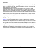
2.3 Commutation Waveforms
In general, in a bi-phase motor design, alternate coils are tied together and give a single connection to
the driver. In this design, the driver connection for coil A and coil C is called L1 (see Figure 2-1). Similarly,
the driver connection for coil B and coil D is called L2. Driving to either of the connections will energize a
coil-pair. The commutation waveform is shown in Figure 2-2. The coil driving period is aligned with the
Hall sensor output. When the sensor output toggles, coil driving is stopped, the coils are de-energized for
a period of time before the next coil-pair is energized.
Figure 2-2. Bi-Phase BLDC Motor Commutation Waveform
2.4 Speed Control
Motor speed is normally defined as the mechanical revolution per one minute of time (rpm). In electrical
terms, one commutation contributes to 90 degrees of a revolution. Thus, control the time taken per
commutation can effectively control the overall speed. One commutation step includes a dead-time
(where the coils are not energized) and the coils energization time. The whole commutation period could
be considered as a pulse width modulation (PWM) output cycle. The PWM period defines the motor speed
in this case. The coils energization time is, in fact, the PWM driving period which is defined by the time
that the coils are energized until the Hall sensor is toggled. The Hall sensor output indicates the position
of the rotor and defines the time to switch to the next commutation step.
In this design the motor speed or the PWM period is continuously monitored. It is a closed-loop control
design. If the motor speed is faster (PWM period is shorter) than the target value, the dead-time duration
is extended until the target PWM period is reached. Similarly, when the motor speed is slower than the
target value, the dead-time duration is shortened.
The rotor starts off at the slowest speed. Shortening the dead-time causes the coils to energize earlier
and the rotor is pushed/pulled to the next pole position sooner, causing motor speed to increase. Similarly,
when the dead-time is extended the rotor hangs loose for a longer time before it is pushed/pulled to the
next pole position. As a result the motor speed decreases. The target motor speed against temperature
is predefined. It is updated periodically based on the information from the temperature sensor.
t
t
t
L1
L2
Hall
Output
Dead
Zone
Dead
Zone
Dead
Zone
Dead
Zone
Dead
Zone
90° of rotation