
User's Manual


Implementation
Variable Speed DC Fan Control using the MC9RS08KA2, Rev. 0
18 Freescale Semiconductor
3.4 Temperature Sensor Measurement
The temperature sensor measurement is performed based on the methodology of an emulated ADC
described in the application note, AN3266 “Getting Started with RS08”.
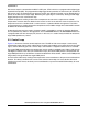
Figure 3-3. Emulated ADC Schematic
The schematic of the emulated ADC in this application is shown in Figure 3-3. The ADC input is the
temperature sensor resistor ladder. When the comparator is not measuring, the capacitor, C, is fully
discharged where the positive terminal of the comparator is pulling low. When the temperature sensor
measurement is required, the comparator is then enabled and the terminal turns to analog input, voltage
across C starts to ramp up. The 8-bit internal modulo timer is used to monitor the time taken for the RC
to charge to a level that matches the voltage across the temperature sensor. The timer counter value is
captured and used as the basis for the emulated ADC conversion.
With a 10kΩ temperature sensor and 7.5kΩ pullup resistor the ADC absolute dynamic range is from 0V
to about 0.57 × V
DD
, i.e. about 2.85V. Timer clock is chosen to be eight times slower than the bus clock,
the timer resolution becomes 2µs. The RC charging profile follows EQ 3-1. Given the RC constant is
4K7Ω × 22nF the timer counter value against the temperature sensor reading with 5V V
DD
is shown in
Table 3-2.
(EQ 3-1)
+
–
MCU BOUNDARY
V
DD
ON-CHIP
COMPARATOR
22nF
C
4k7
R
V
DD
7k5
10k
TEMP SENSOR
VV
DD
1e
t
RC
--------–
–
⎝⎠
⎜⎟
⎛⎞
=