
User's Guide
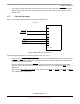
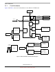
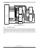
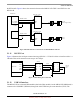
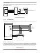
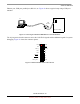
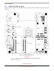
Table Of Contents
- About This Book
- 1 Introduction
- 2 MPC837xE-RDS Board
- 2.1 Board-Level Functions
- 2.1.1 Reset and Reset Configurations
- 2.1.2 External Interrupts
- 2.1.3 Clock Distribution
- 2.1.4 DDR2 SDRAM Controller
- 2.1.5 Local Bus Controller
- 2.1.6 Flash Memory
- 2.1.7 I2C
- 2.1.8 SATA Controller
- 2.1.9 PCI Express Interface (PCI-E & Mini PCI-E)
- 2.1.10 10/100/1000 BaseT Interface
- 2.1.11 RS-232 Port
- 2.1.12 USB 2.0 Interface
- 2.1.13 PCI Subsystem
- 2.1.14 COP/JTAG Port
- 2.2 MPC837xE-RDS Assembly
- 2.3 Connectors
- 2.4 LEDs
- 2.5 MPC837xE-RDS Board Configuration
- 2.6 Specifications
- 2.7 Mechanical Data
- 2.1 Board-Level Functions
- 3 Board Bootup
- 4 MPC837xE-RDS Software
- 5 Unit Assembly
- MPC837xE-RDS

MPC837xE-RDS Board
MPC837xE-RDS, Rev. 1.0
Freescale Semiconductor 17
Preliminary, Subject to Change without Notice
the RTL8211B. Figure 8 shows the connection between the MPC837xE eTSEC1 and eTSEC2 to the
RTL8211B.
Figure 8. RGMII Interface Connection for 10/100/1000 BaseT Ethernet
2.1.11 RS-232 Port
Figure 9 illustrates the serial port connection using a SP3232 3.3 V RS-232 driver to interface with a 2 x
5 Header. This serial connection runs at up to 115.2 Kbps.
Figure 9. UART Debug Port Connection
2.1.12 USB 2.0 Interface
The MPC837xE has a internal USB modules (dual-role (DR) module). On the MPC837xE-RDS board, it
connects to the USB PHY (USB3300) through the 8-bit UTMI low-pin-count interface (ULPI). The
RJ-45
eTSEC1
MPC837xE
RTL8211B
MDIO
MDC
EC_MDIO
EC_MDC
RGMII interface
PHY addr = 0x02
eTSEC2
3.3 V
LVDD2
RJ-45
(Enet0, supports PoE)
(Enet1)
3.3 V
LVDD1
RGMII interface
RTL8211B
MDIO
MDC
PHY addr = 0x03
SP3232
TXD
RXD
CTS
RX
TX
TX
DO
DI
DI
MPC837xE
RTS
RS-232
Serial
Port
RXRXD
RTS
TXD
CTS
DO
UART0
4
6
8
3
7
5
2
1
910
TXD
RTS