
User's Guide
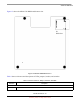
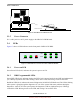
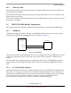
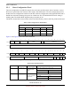
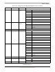
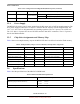
Table Of Contents
- About This Book
- 1 Introduction
- 2 MPC837xE-RDS Board
- 2.1 Board-Level Functions
- 2.1.1 Reset and Reset Configurations
- 2.1.2 External Interrupts
- 2.1.3 Clock Distribution
- 2.1.4 DDR2 SDRAM Controller
- 2.1.5 Local Bus Controller
- 2.1.6 Flash Memory
- 2.1.7 I2C
- 2.1.8 SATA Controller
- 2.1.9 PCI Express Interface (PCI-E & Mini PCI-E)
- 2.1.10 10/100/1000 BaseT Interface
- 2.1.11 RS-232 Port
- 2.1.12 USB 2.0 Interface
- 2.1.13 PCI Subsystem
- 2.1.14 COP/JTAG Port
- 2.2 MPC837xE-RDS Assembly
- 2.3 Connectors
- 2.4 LEDs
- 2.5 MPC837xE-RDS Board Configuration
- 2.6 Specifications
- 2.7 Mechanical Data
- 2.1 Board-Level Functions
- 3 Board Bootup
- 4 MPC837xE-RDS Software
- 5 Unit Assembly
- MPC837xE-RDS

MPC837xE-RDS, Rev. 1.0
24 Freescale Semiconductor
Preliminary, Subject to Change without Notice
MPC837xE-RDS Board
Figure 16. Installation of a Mini PCI Card
2.3.5 Power Connector
J13 is a DC jack for a 48 V power supply to the MPC837xE-RDS board.
2.4 LEDs
Figure 17 shows 9 LED indicators on the front panel of MPC837xE-RDS.
Figure 17. LED Indicators on the Front Panel of MPC837xE-RDS
2.4.1 Power-on LED
Green Power LED (D15): indicates the system is power-on if lit.
2.4.2 RDS Programmable LEDs
Green WiFi LED (D14): indicates whether the WiFi Card is inserted and activated (SW not implemented
yet). GPIO1[10] controls this LED. Writing 0 turns on the LED, and writing 1 turns off the LED.
Red DIAG LED (D11): indicates the status of diagnostics for MPC837xE-RDS board. The LED is flashing
when system is going through the diagnostics. It is on if the system finds some problems during the
diagnostics. And it is off if the system passes the diagnostics (SW not implemented yet). GPIO1[9]
controls this LED. Writing 0 turns on the LED, and writing 1 turns off the LED.
M
i
n
i
P
C
I
C
a
r
d
1
.
I
n
se
r
t
t
h
e
c
a
r
d
2. Press downward
POWER WiFi DIAG
LAN
WAN
1000
100
10