
User's Guide
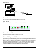
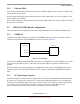
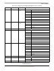
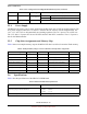
Table Of Contents
- About This Book
- 1 Introduction
- 2 MPC837xE-RDS Board
- 2.1 Board-Level Functions
- 2.1.1 Reset and Reset Configurations
- 2.1.2 External Interrupts
- 2.1.3 Clock Distribution
- 2.1.4 DDR2 SDRAM Controller
- 2.1.5 Local Bus Controller
- 2.1.6 Flash Memory
- 2.1.7 I2C
- 2.1.8 SATA Controller
- 2.1.9 PCI Express Interface (PCI-E & Mini PCI-E)
- 2.1.10 10/100/1000 BaseT Interface
- 2.1.11 RS-232 Port
- 2.1.12 USB 2.0 Interface
- 2.1.13 PCI Subsystem
- 2.1.14 COP/JTAG Port
- 2.2 MPC837xE-RDS Assembly
- 2.3 Connectors
- 2.4 LEDs
- 2.5 MPC837xE-RDS Board Configuration
- 2.6 Specifications
- 2.7 Mechanical Data
- 2.1 Board-Level Functions
- 3 Board Bootup
- 4 MPC837xE-RDS Software
- 5 Unit Assembly
- MPC837xE-RDS

MPC837xE-RDS Board
MPC837xE-RDS, Rev. 1.0
Freescale Semiconductor 25
Preliminary, Subject to Change without Notice
2.4.3 Ethernet LEDs
Green Link1000 LEDs (D9): indicate the link speed is 1000M on WAN and LAN. (The top LED for LAN
and the bottom one for WAN)
Green Link100 LEDs (D8): indicate the link speed is 100M on WAN and LAN. (The top LED for LAN
and the bottom one for WAN)
Green Link10 LEDs (D7): indicate the link speed is 10M on WAN and LAN. (The top LED for LAN and
the bottom one for WAN)
2.5 MPC837xE-RDS Board Configuration
This section describes the operational mode and configuration options of the MPC837xE-RDS board.
2.5.1 EEPROM
The MPC837xE-RDS board has an on-board serial EEPROM. MPC837xE acts as I
2
C master and it is
connected to the M24256 serial EEPROM using I2C1 as shown in Figure 18.
Figure 18. I2C EEPROM
You can use the M24256 serial EEPROM to store the reset configuration word of the MPC837xE, as well
as store the configuration registers’ values and user program if the boot sequencer of MPC837xE is
enabled.
For more details about programming the reset configuration word value in I
2
C EEPROM and the boot
sequencer mode, refer to the MPC8379ERM. The I
2
C address of the M24256 EEPROM on the bus is
0x50.
2.5.2 PCI Operating Frequency
An M66EN input pin determines the AC timing of the PCI interface. On the MPC837xE-RDS board, the
PCI agent card—connected to a mini PCI slot—determines the M66EN signal level. If a 33-MHz-only
card is inserted, the M66EN signal is driven to 0 by the PCI agent card according to the PCI specification,
or it is driven to 1 if it can perform at 66 MHz. A NOT gate inverts the signal and drives the
CFG_CLKIN_DIV input pin so the system clock continues at the same frequency.
I2C1-SCL
I
2
C EEROM
M24256
MPC837xE
SCL
SDA
I2C1-SDA
I
2
C Address = 0x50