
User's Guide
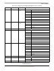
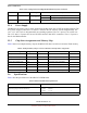
Table Of Contents
- About This Book
- 1 Introduction
- 2 MPC837xE-RDS Board
- 2.1 Board-Level Functions
- 2.1.1 Reset and Reset Configurations
- 2.1.2 External Interrupts
- 2.1.3 Clock Distribution
- 2.1.4 DDR2 SDRAM Controller
- 2.1.5 Local Bus Controller
- 2.1.6 Flash Memory
- 2.1.7 I2C
- 2.1.8 SATA Controller
- 2.1.9 PCI Express Interface (PCI-E & Mini PCI-E)
- 2.1.10 10/100/1000 BaseT Interface
- 2.1.11 RS-232 Port
- 2.1.12 USB 2.0 Interface
- 2.1.13 PCI Subsystem
- 2.1.14 COP/JTAG Port
- 2.2 MPC837xE-RDS Assembly
- 2.3 Connectors
- 2.4 LEDs
- 2.5 MPC837xE-RDS Board Configuration
- 2.6 Specifications
- 2.7 Mechanical Data
- 2.1 Board-Level Functions
- 3 Board Bootup
- 4 MPC837xE-RDS Software
- 5 Unit Assembly
- MPC837xE-RDS

MPC837xE-RDS Board
MPC837xE-RDS, Rev. 1.0
Freescale Semiconductor 31
Preliminary, Subject to Change without Notice
Addressing: Total address range
Flash memory (local bus)
DDR SDRAM
4 Gbyte (32 address lines)
64 Mbyte NOR Flash
512 Mbyte DDR2 SDRAM at DDR400
Operating temperature 0
o
C to 70
o
C (room temperature)
Storage temperature –25
o
C to 85
o
C
Relative humidity 5% to 90% (noncondensing)
PCB dimensions:
Length
Width
Thickness
6693 mil
6693 mil
67 mil
Table 9. MPC837xE-RDS Board Specifications (continued)
Characteristics Specifications